Analog Discovery 2 Reference Manual
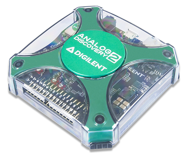
The Digilent Analog Discovery 2™, developed in conjunction with Analog Devices®, is a multi-function instrument that allows users to measure, visualize, generate, record, and control mixed signal circuits of all kinds. The low-cost Analog Discovery 2 is small enough to fit in your pocket, but powerful enough to replace a stack of lab equipment, providing engineering students, hobbyists, and electronics enthusiasts the freedom to work with analog and digital circuits in virtually any environment, in or out of the lab.


Oscilloscope
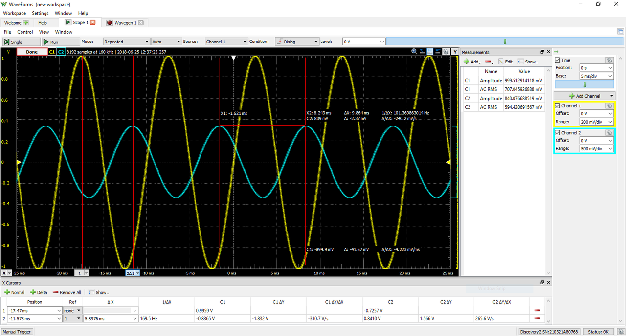
The Analog Discovery 2 can be used with WaveForms' Oscilloscope instrument to capture analog input data via the analog input (“Scope”) channels, using either BNC cables or MTE cables. When this instrument is used, the Analog Discovery 2's analog input channels act as a two-channel, 14-bit, 100 MS/s oscilloscope.
You can use the BNC Adapter to use BNC cables with the oscilloscope. Please remember when using BNC cables that the oscilloscope channels are single-ended and the circuit under test must still share a common ground with the Analog Discovery 2. With BNC cables, the analog input channels have a substantially higher bandwidth than with MTE cables.
When used with MTE cables, the oscilloscope channels' + and - pins are differentially paired. The - pins can be attached to a non-ground circuit net, but the circuit under test must still share a common ground with the Analog Discovery 2.
Since the Analog Discovery 2's analog input channels are shared, the Oscilloscope instrument cannot be used at the same time as the Voltmeter, Data Logger, Spectrum Analyzer, Network Analyzer, or Impedance Analyzer instruments.
For more information on the analog input (“Scope”) channels, please visit the Analog Discovery 2 Specifications. For a walkthrough of the different features of WaveForms' Oscilloscope instrument, please visit the Using the Oscilloscope guide.
Features
- Triggering: edge, pulse, transition, hysteresis, and many others
- Cross-triggering with Logic Analyzer, Waveform Generator, Pattern Generator, or external trigger
- Sampling modes: average, decimate, min/max
- Mixed signal visualization (analog and digital signals share same view pane)
- Real-time views: FFTs, XY plots, histograms, spectrograms, and others
- Multiple math channels with complex functions
- Cursors with advanced data measurements
- Captured data files can be exported in standard formats
- Scope configurations can be saved, exported, and imported
- Important Note: Grounding Circuitry
-
Despite the fact that the Analog Discovery 2 analog input channels are fully differential, a GND connection to the circuit under test is required to provide a stable common mode voltage.
The Analog Discovery 2's GND reference is connected to the USB GND. Depending on the PC powering scheme, and other PC connections (Ethernet, audio, etc. – which might also be grounded) the Analog Discovery 2 GND reference might be connected to the whole GND system and ultimately to the power network protection (earth ground). The circuit under test might also be connected to earth or possibly floating.
For safety reasons, it is the user’s responsibility to understand the powering and grounding scheme and to make sure that there is a common GND reference between the Analog Discovery 2 and the circuit under test, and that the common mode and differential voltages do not exceed specifications. Furthermore, for distortion-free measurements, the common mode and differential voltages need to meet specifications.
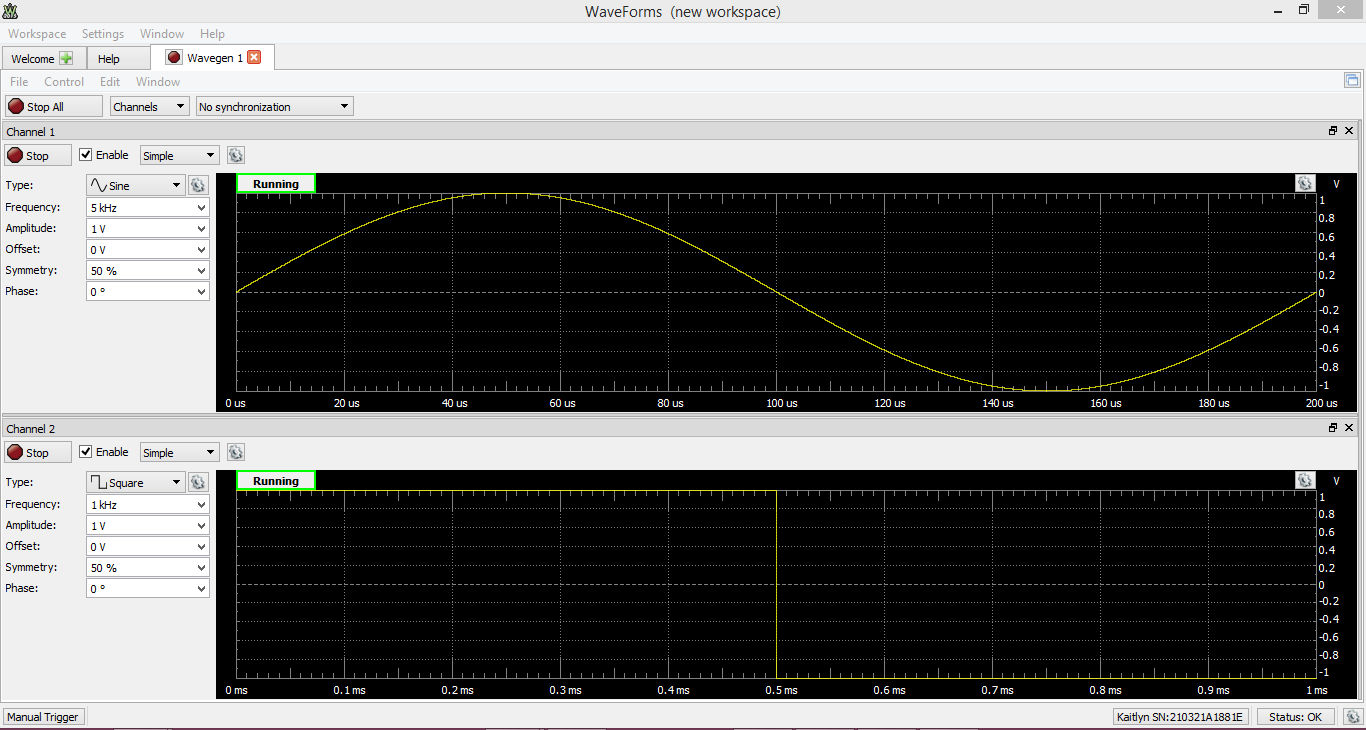
Waveform Generator
The Analog Discovery 2 can be used with WaveForms' Wavegen instrument to output analog voltage waves via either BNC (BNC Adapter) cables or MTE cables. Wavegen converts 14-bit digital samples to analog at a rate of up to 100 MS/s on each of two channels. When Wavegen is used, the Analog Discovery 2's analog output channels act as an Arbitrary Waveform Generator. The instrument supports everything from simple waveforms like Sine and Triangle waves, up to more complicated functions like AM and FM modulation. Custom sets of samples can be defined by the user in applications like Excel and imported to WaveForms.
Each waveform generator channel is considered a single ended pin, however, a connected circuit must share a ground with the Analog Discovery 2.
Since the Analog Discovery 2's analog output channels are shared, the Waveform Generator instrument cannot be used at the same time as the Network Analyzer, or Impedance Analyzer instruments.
For more information on the analog output (Wavegen) channels, please visit the Analog Discovery 2 Specifications. For a walkthrough of the different features of WaveForms' Waveform Generator instrument, please visit the Using the Waveform Generator guide.
Features
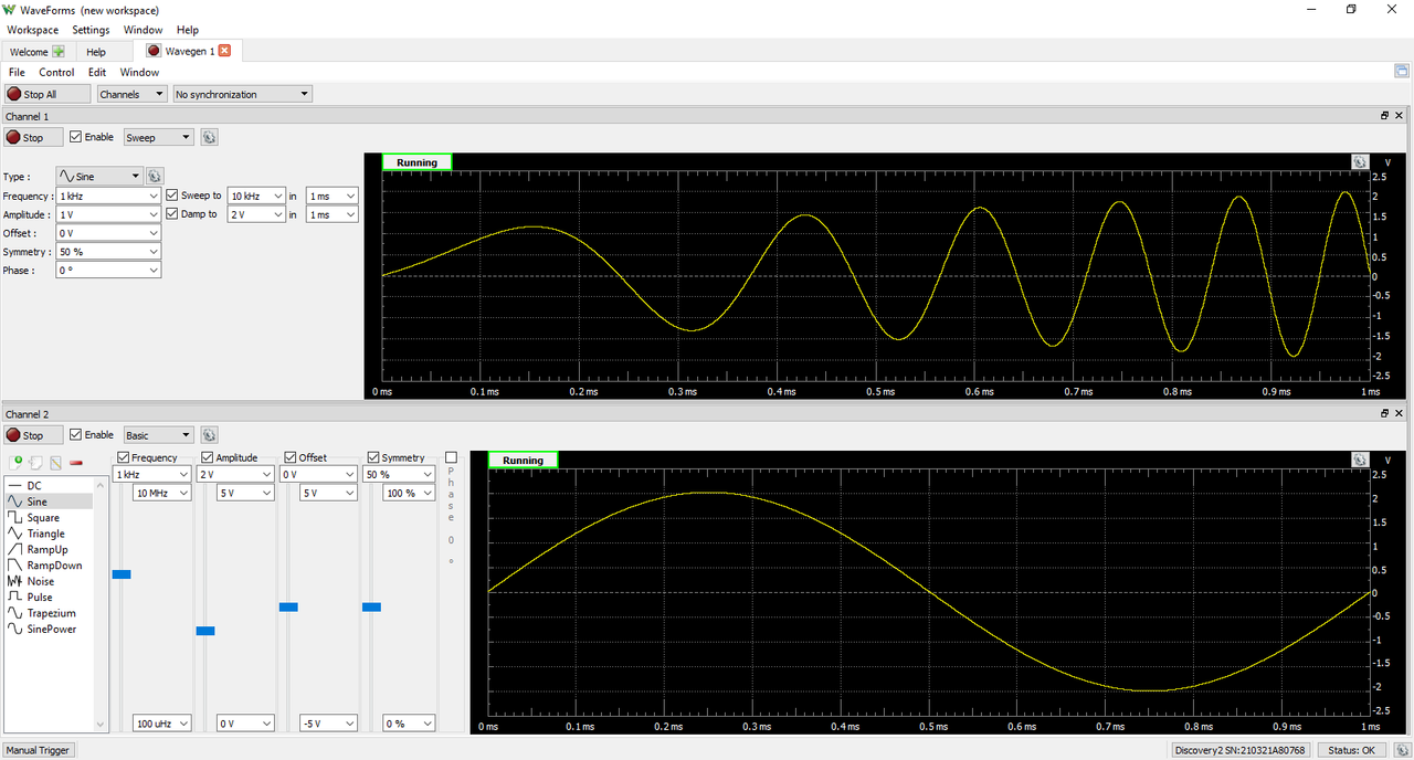
- Standard waveforms: sine, triangle, sawtooth, noise, and many others
- Advanced waveforms: Sweeps, AM, FM
- User-defined arbitrary waveforms: defined within WaveForms software user interface or using standard tools (e.g. Excel)
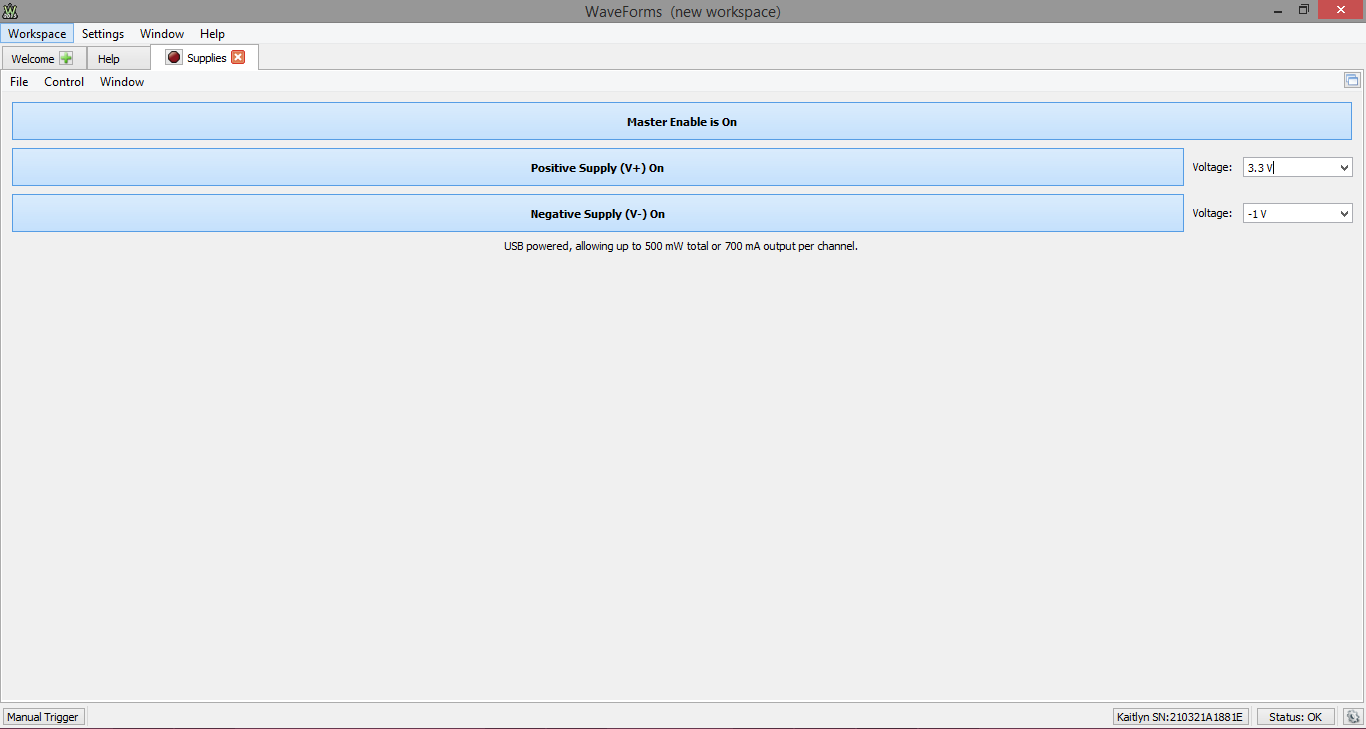
Power Supplies
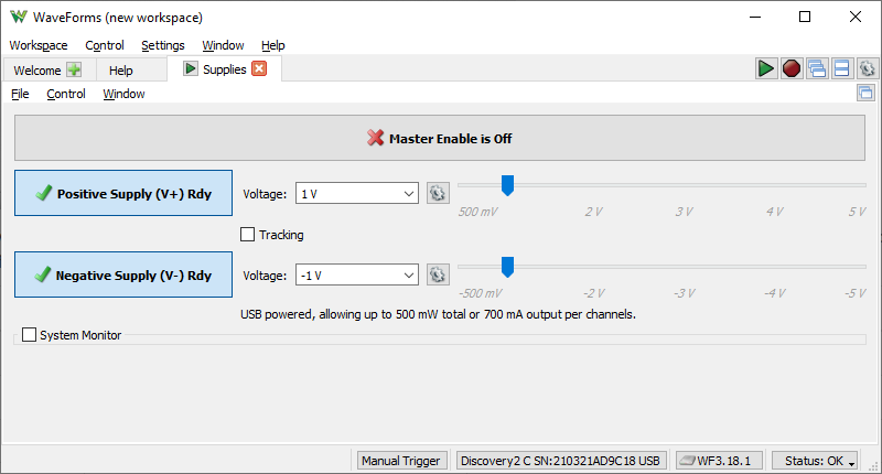
The Analog Discovery 2 has two variable power supply rails that can be used to power circuits under test. These rails can be set to voltage levels between 0.5 V to 5 V and -0.5 V to -5 V respectively, through the use of WaveForms' “Supplies” instrument.
For more information on the programmable power supplies, please visit the Analog Discovery 2 Specifications. For a walkthrough of the different features of WaveForms' Power Supplies instrument, please visit the Using the Power Supplies guide.
Features
- Two programmable power supplies (0.5 V to 5 V , -0.5 V to -5 V). The maximum available output current and power depend on the Analog Discovery 2 powering choice.
Voltmeter

The Analog Discovery 2's analog input pins can be used with WaveForms' Voltmeter instrument to act as a simple voltmeter. DC voltages, AC RMS voltages, and True RMS voltages can be viewed for each of the two Scope channels.
Since the Analog Discovery 2's analog input channels are shared, the Voltmeter instrument cannot be used at the same time as the Oscilloscope, Data Logger, Spectrum Analyzer, Network Analyzer, or Impedance Analyzer instruments.
For more information on the analog input (“Scope”) channels, please visit the Analog Discovery 2 Specifications. For a walkthrough of the different features of WaveForms' Voltmeter instrument, please visit the Using the Voltmeter guide.
Features
- Measurements: DC, AC RMS, True RMS
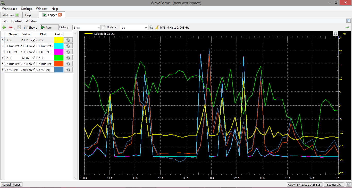
Data Logger
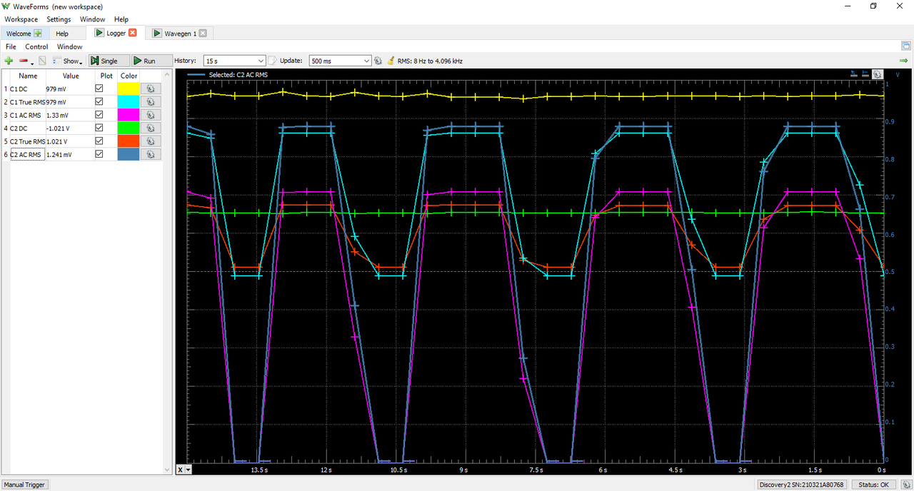
The Analog Discovery 2 can be used with WaveForms' Logger instrument in order to capture large buffers of analog input data on the Scope pins.
The Data Logger can capture buffers of data at update rates of up to 10 samples per second. The maximum duration of a log is dependent on the update rate, but at the extreme, can run for over a thousand hours.
Since the Analog Discovery 2's analog input channels are shared, the Data Logger instrument cannot be used at the same time as the Oscilloscope, Voltmeter, Spectrum Analyzer, Network Analyzer, or Impedance Analyzer instruments.
For more information on the analog input (Logger) channels, please visit the Analog Discovery 2 Specifications. For a walkthrough of the different features of WaveForms' Data Logger instrument, please visit the Using the Data Logger guide.
Features
- Measurements: DC, AC RMS, True RMS, with Averages, Minimums, and Maximums
- Up to 24 hours of data logged at a 1Hz sample rate
- Scriptable conversion functions
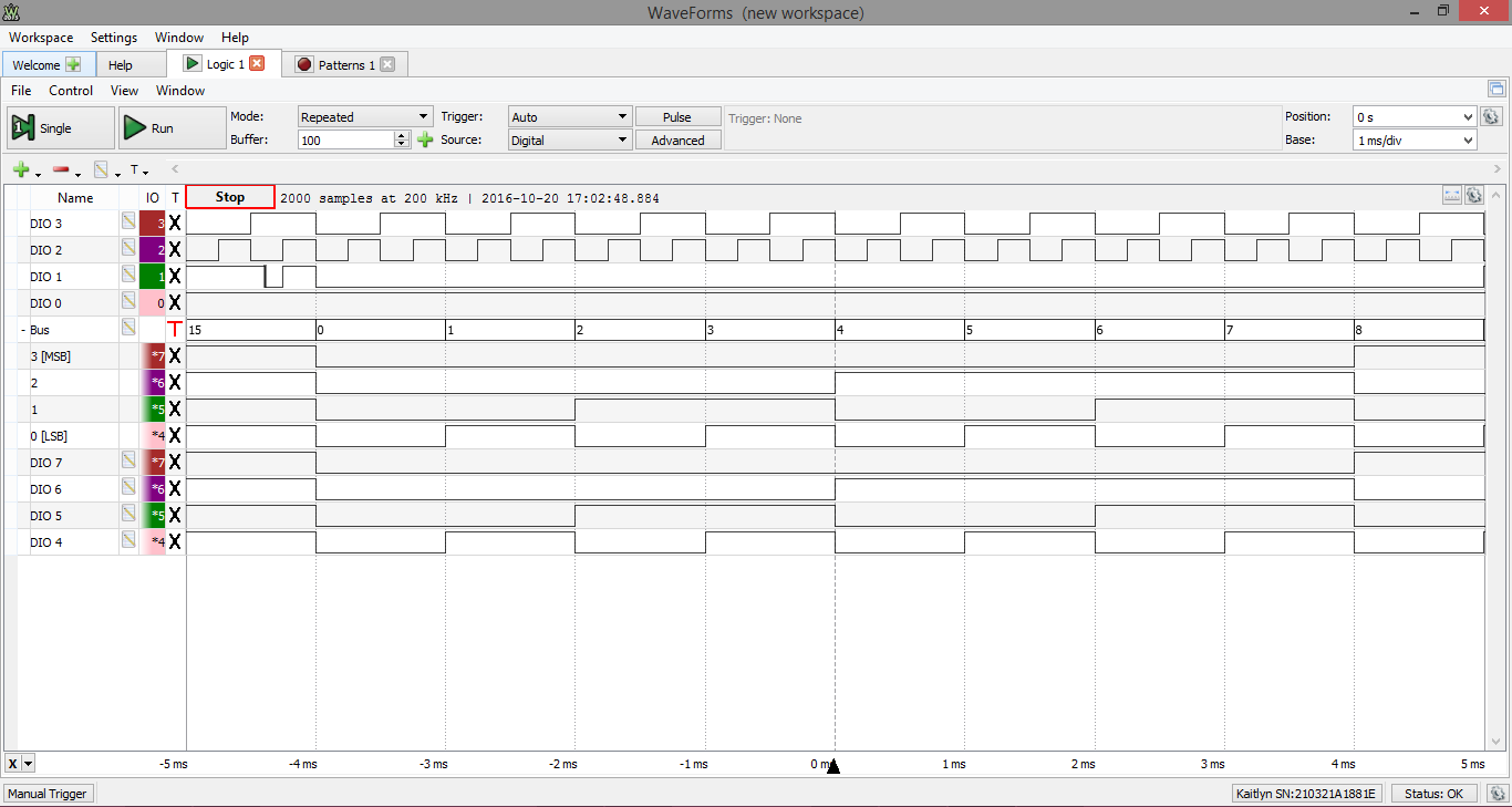
Logic Analyzer
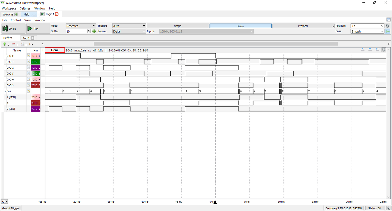
The Analog Discovery 2 can be used with WaveForms' “Logic” instrument to act as a Logic Analyzer. When used this way, the 16 digital input/output channels are configured to capture high/low logic states on connected pins. These channels are capable of interfacing with 3.3 V and 1.8 V logic signals and are tolerant to voltages of up to 5V.
Individual input/output channels can be grouped as buses and protocols. Protocol groups can be used to view the decoded contents of packets of many common communications protocols, including SPI, I2C, UART, CAN, and I2S.
Signal states, decoded bus values, and decoded protocols can be used to trigger a Logic Analyzer capture. Protocol triggers include protocol-specific events, like start of transmission, end of transmission, or packet contents matching a value.
Digital input/output channels used by the Logic Analyzer instrument can still be used by other instruments using the same digital input/output channels.
For more information on the digital input/output channels, please visit the Analog Discovery 2 Specifications. For a walkthrough of the different features of WaveForms' Logic Analyzer instrument, please visit the Using the Logic Analyzer guide.
Features
- Multiple trigger options including pin change, bus pattern, and many others
- Cross-triggering between Analog input channels, Logic Analyzer, Pattern Generator, or external trigger
- Interpreter for SPI, I2C, UART, CAN, I2S, 1-Wire, parallel buses
- Scripted custom protocols
- Data file import/export using standard formats
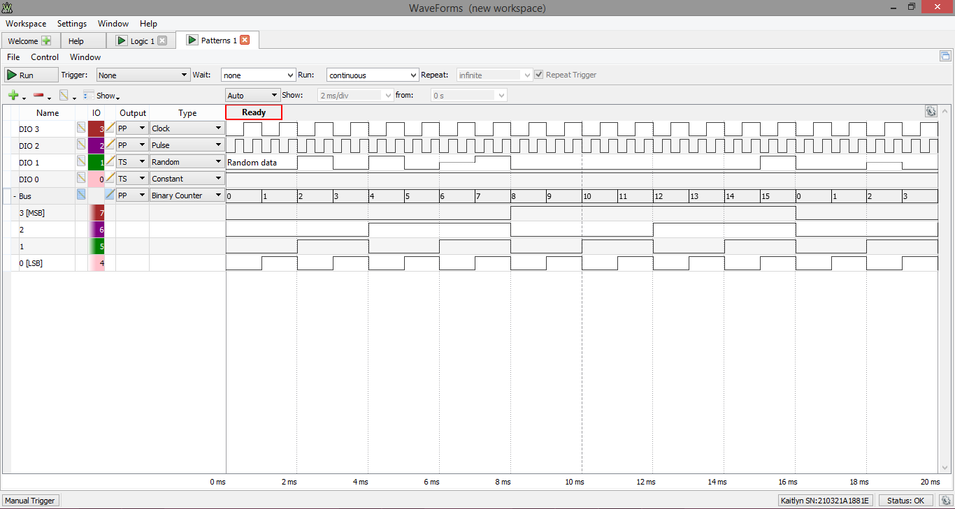
Pattern Generator
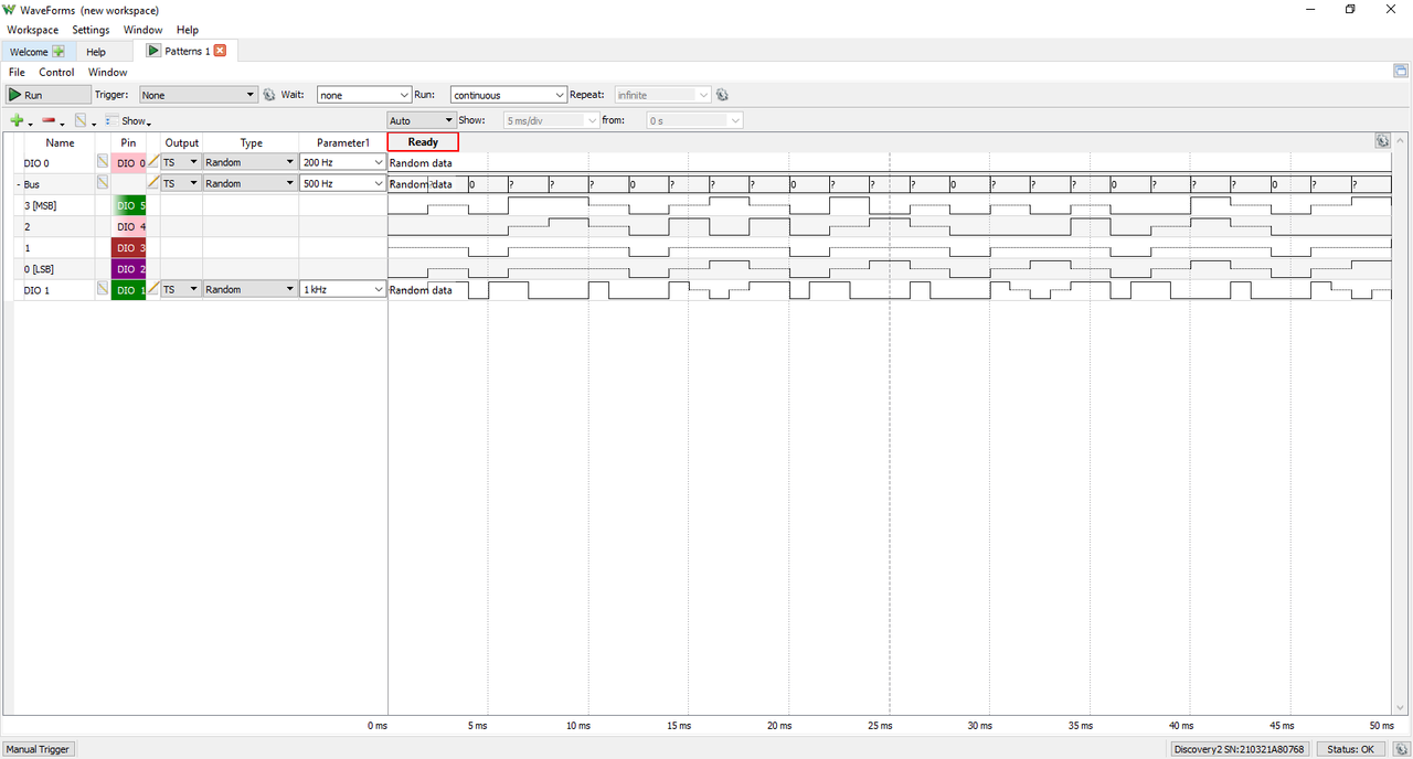
The Analog Discovery 2 can be used with WaveForms' “Patterns” instrument to generate logic signal sequences on the digital input/output pins.
The pins can be configured to be push/pull, open drain, open source, or three-state logic. The logic high output voltage level is 3.3V. Sample rates can go as high as 100 MS/s.
Digital input/output channels used by the Pattern Generator instrument can still be used by other instruments using the same digital input/output channels, however, other instruments can only use these shared channels as inputs.
For more information on the digital input/output channels, please visit the Analog Discovery 2 Specifications. For a walkthrough of the different features of WaveForms' Pattern Generator instrument, please visit the Using the Pattern Generator guide.
Features
- Customized visualization for signals and buses
- User defined patterns: Truth-table based ROM logic
- Data file import/export using standard formats
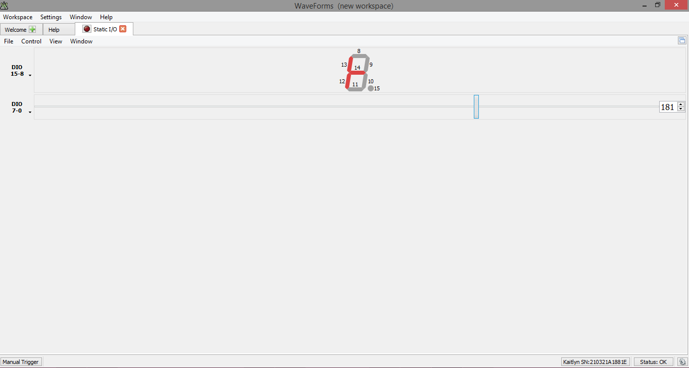
Digital I/O
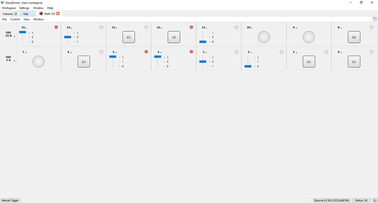
The Analog Discovery 2 can be used with WaveForms' Static I/O instrument to emulate a variety of user input/output devices on the digital input/output pins. Virtual LEDs, buttons, switches, sliders, and displays can be assigned to specific digital I/O pins, and interacted with within the WaveForms user interface.
The Analog Discovery 2's digital input/output channels use a 3.3v V logic standard for output, and can accept either 1.8 V or 3.3 V logic signals as inputs. The digital input/output pins are tolerant to input signals up to 5V.
Digital input/output channels used by the Static I/O instrument can still be used by other instruments using the same digital input/output channels, however, other instruments can only use these shared channels as inputs.
For more information on the digital input/output channels, please visit the Analog Discovery 2 Specifications. For a walkthrough of the different features of WaveForms' Static I/O instrument, please visit the Using the Static I/O guide.
Features
- Virtual I/O devices (LEDs, buttons, switches, & displays)
- Customized visualization options available
- Important Note: Voltage Limits
- To prevent damage to the device, care must be taken not to drive input signals to the digital input/output channels over 5V.
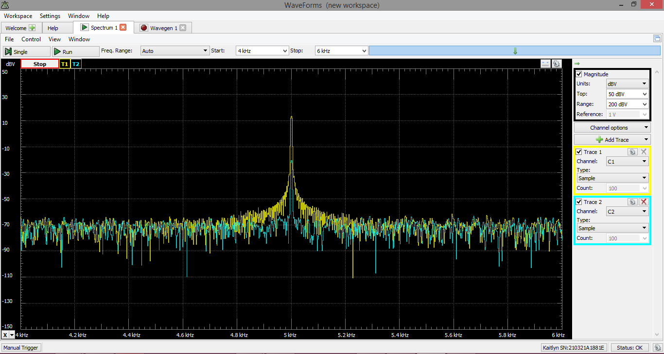
Spectrum Analyzer

The Analog Discovery 2 can be used with WaveForms' Spectrum instrument to view the power of frequency-domain components of analog signals captured on the analog input channels.
Since the Spectrum Analyzer instrument uses the same hardware resources as the Oscilloscope, Network Analyzer, and Impedance Analyzer instruments, it cannot be used at the same time as these other instruments.
Since the Analog Discovery 2's analog input channels are shared, the Oscilloscope instrument cannot be used at the same time as the Oscilloscope, Voltmeter, Data Logger, Network Analyzer, or Impedance Analyzer instruments.
For more information on the analog input channels, please visit the Analog Discovery 2 Specifications. For a walkthrough of the different features of WaveForms' Spectrum Analyzer instrument, please visit the Using the Spectrum Analyzer guide.
Features
- Power spectrum algorithms: FFT, CZT
- Frequency range modes: center/span, start/stop
- Frequency scales: linear, logarithmic
- Vertical axis options: voltage-peak, voltage-RMS, dBV, and dBu
- Windowing: options: rectangular, triangular, hamming, cosine, and many others
- Cursors and automatic measurements: noise floor, SFDR, SNR, THD and many others
- Data file import/export using standard formats
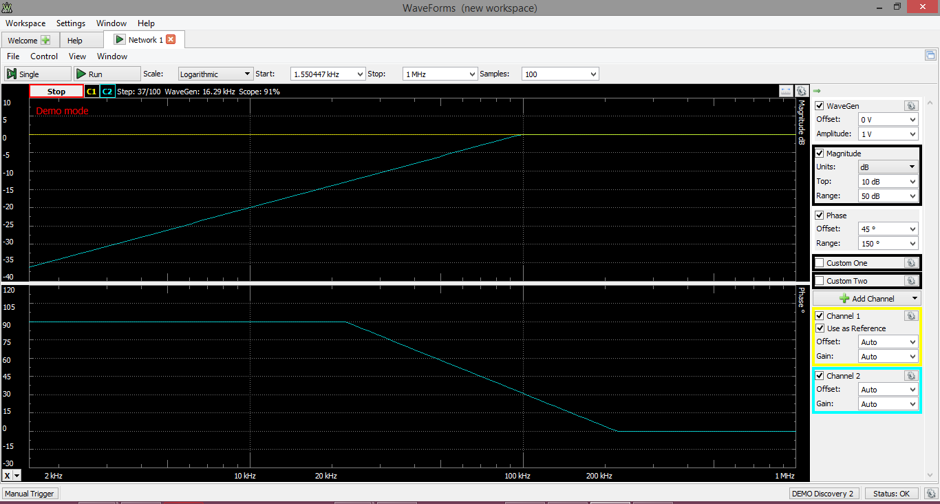
Network Analyzer
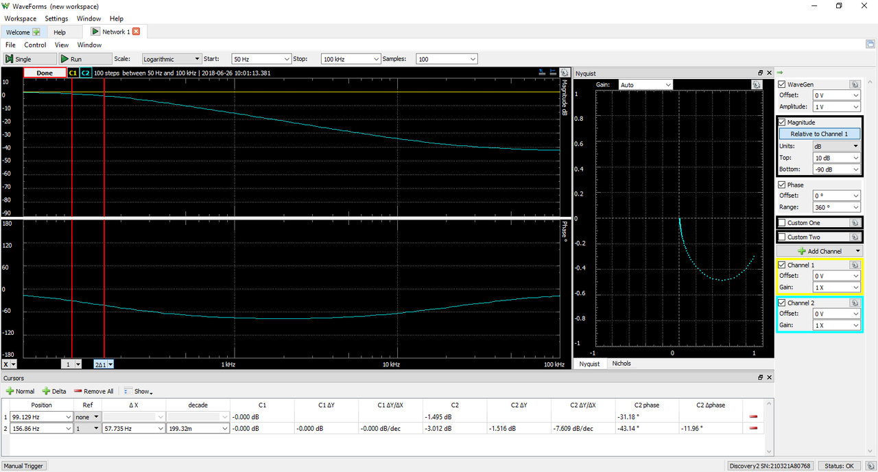
The Analog Discovery 2 can be used with WaveForms' “Network” instrument to view the amplitude and phase response of a circuit under test. Nichols and Nyquist plots can also be viewed with this instrument.
A sweep is performed in order to test the response of the circuit at varying frequencies. The wave used to perform this sweep can be customized and uses the same resources as the Waveform Generator instrument.
The Network Analyzer instrument uses the analog output and analog input channels of the Analog Discovery 2 to probe a test circuit. The Network Analyzer can be configured to use an external signal to provide input to the circuit under test, rather than using the analog output channels.
Since the Analog Discovery 2's analog input and output channels are shared, the Network Analyzer instrument cannot be used at the same time as the Oscilloscope, Waveform Generator, Voltmeter, Data Logger, Spectrum Analyzer, or Impedance Analyzer instruments.
For more information on the analog output and analog input channels, please visit the Analog Discovery 2 Specifications. For a walkthrough of the different features of WaveForms' Network Analyzer instrument, please visit the Using the Network Analyzer guide.
Features
- Available diagrams: Bode, Nichols, Nyquist, and FFTs
- Settable input amplitude and offset
- Analog input records response at each frequency
Impedance Analyzer
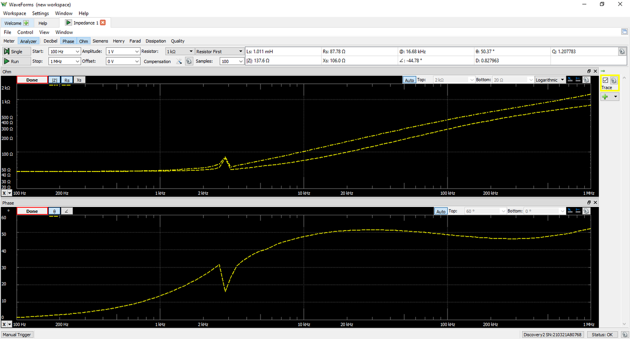
The Analog Discovery 2 can be used with WaveForms' Impedance instrument to view a wide variety of frequency response characteristics of a circuit under test. Input, Phase, Voltage, Current, Impedance, Admittance, Inductance, Factor, and Nyquist plots are all available. In addition, Custom plots can be used to present the results of a wide variety of different mathematical operations on buffered data. Check out the Impedance Analyzer Adapter for more information
A sweep is performed in order to test the response of the circuit at varying frequencies. The signal used to perform the sweep can be selected from a variety of presets, with configurable amplitude and offset. An external network analyzer reference circuit can be selected from a variety of options.
The Impedance Analyzer instrument uses the analog output channels and analog input channels of the Analog Discovery 2 to probe a test circuit.
Since the Analog Discovery 2's analog input and output channels are shared, the Impedance Analyzer instrument cannot be used at the same time as the Oscilloscope, Waveform Generator, Voltmeter, Data Logger, Spectrum Analyzer, or Network Analyzer instruments.
For more information on the analog output and analog input channels, please visit the Analog Discovery 2 Specifications. For a walkthrough of the different features of WaveForms' Impedance Analyzer instrument, please visit the Using the Impedance Analyzer guide.
Features
- Chart views for Voltage, Current, Impedance, Admittance, Capacitance, and others
- Alternative simple Meter view
- Selectable external compensation circuit
- Data file export using standard formats
Curve Tracer

The Analog Discovery 2 can be used with WaveForms' Tracer instrument to plot the characteristic I-V curves of devices like diodes, NPN and PNP transistors, and both P- and N-type FETs.
A reference circuit external to the Analog Discovery 2 is required, or the Transistor Tester Adapter provides this circuit out of the box. For more information on constructing a reference circuit and using the Tracer more generally, check out the Using the WaveForms Curve Tracer guide.
Circuit diagrams are provided in WaveForms, regardless of whether the Transistor Tester Adapter is used or not, which indicate how each leg of the device under test is to be connected to the Analog Discovery 2 or the adapter.
Since the Analog Discovery 2's analog input and output channels are shared, the Curve Tracer instrument cannot be used at the same time as the Oscilloscope, Waveform Generator, Voltmeter, Data Logger, Spectrum Analyzer, or Network Analyzer instruments.
Features
- Works with diodes, NPN and PNP transistors, and P- and N-Type FETs
- Performs a variety of selectable measurements depending on the device under test, covering many combinations of base/collector/emitter and drain/gate/source voltages and currents
- Settable voltage sweep ranges and current limits
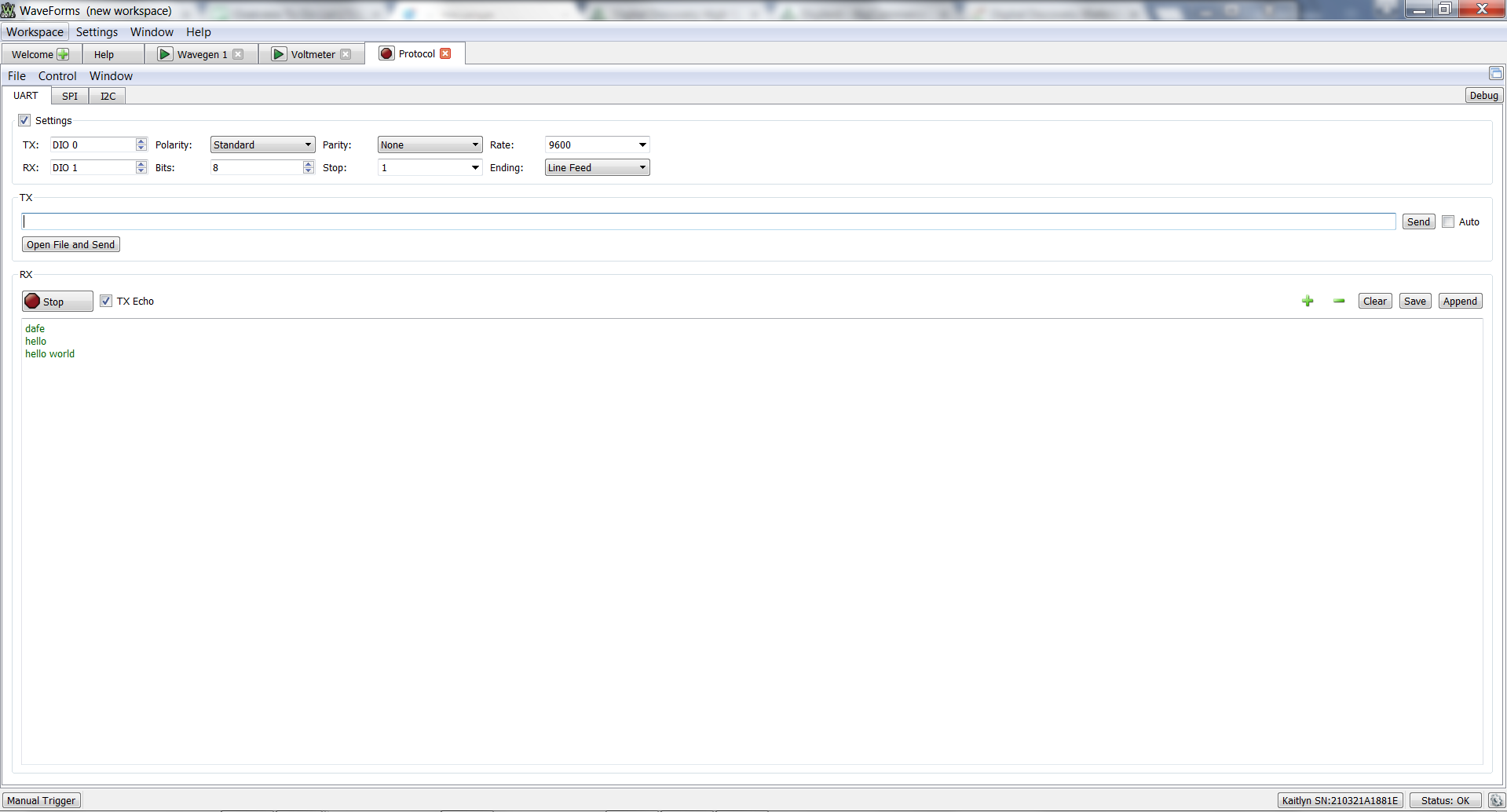
Protocol Analyzer
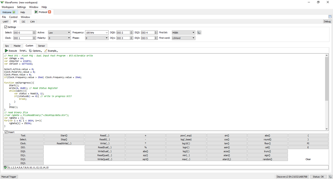
The Analog Discovery 2 can be used with WaveForms' “Protocol” instrument to work with common communications protocols. UART, SPI, I2C, and CAN transactions can be received, transmitted, and/or spied upon by the Analog Discovery 2 using any of the digital input/output channels.
Custom scripts can be written within the Protocol Analyzer instrument to generate sequences of SPI or I2C transactions.
Since it uses the same hardware resources as the Logic Analyzer and Pattern Generator instruments, the Protocol Analyzer cannot be used at the same time as these instruments.
For more information on the digital input/output channels, please visit the Analog Discovery 2 Specifications. For a walkthrough of the different features of WaveForms' Protocol Analyzer instrument, please visit the Using the Protocol Analyzer guide.
Features
- Supports UART, SPI, I2C, and CAN protocols
- Scriptable transaction sequences for SPI and I2C
- Configurable data rates, modes, and others
- Send/receive directly from/to data files
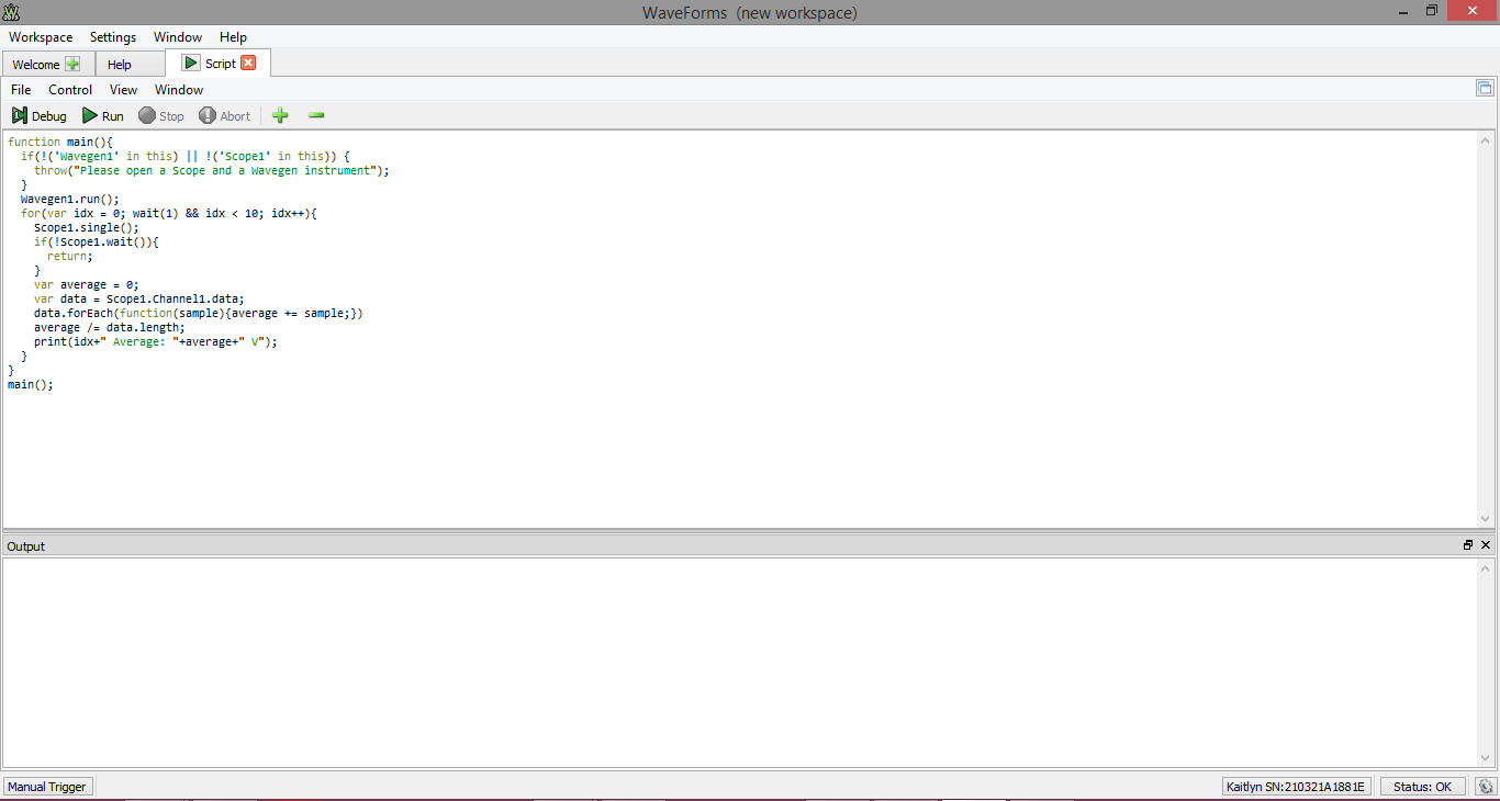
WaveForms Script Editor
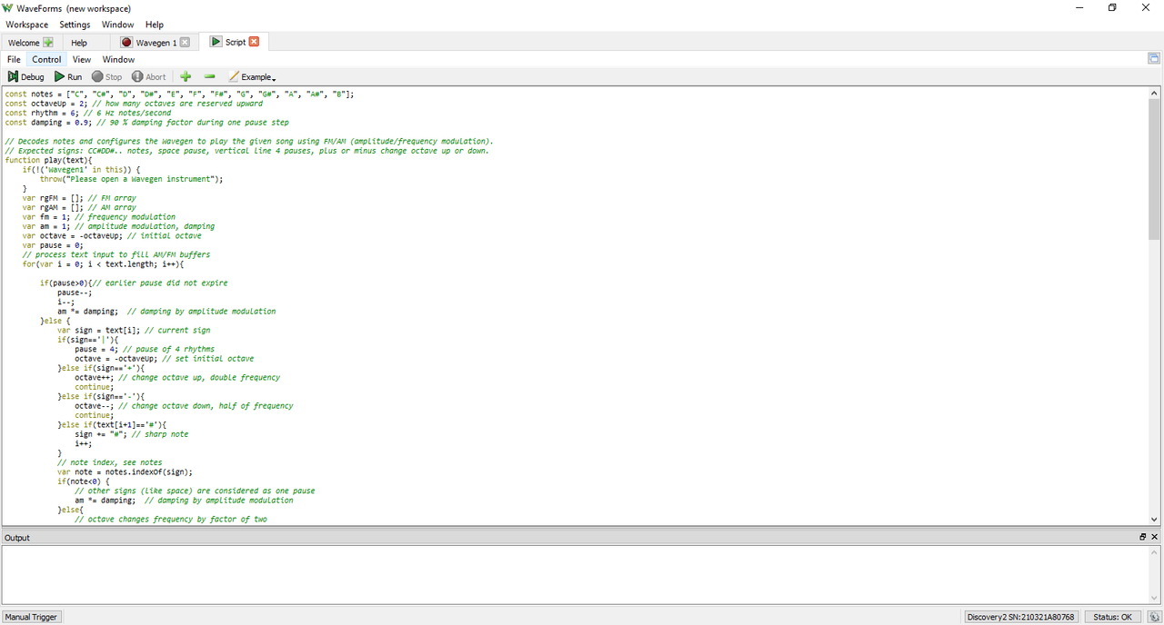
Each of WaveForms' instruments can be controlled through scripts within the WaveForms application itself. WaveForms' “Script” instrument allows the user to write and run javascript code that can control the rest of the application through an extensive API. This allows the user to configure and run many instruments at the same time, in an easily repeatable way.
A variety of code examples are available in the application to aid in learning to write WaveForms scripts. Additional resources for writing scripts can be found on the Test and Measurement section of the Digilent Forum.
A plot pane within the Script instrument itself can be used to integrate data from many different instruments, and display it in a highly customizable way.
For a walkthrough of the different features of WaveForms' Script instrument, please visit the Using Scripts guide.
Features
- Available within the WaveForms application
- Simultaneous control of all instruments through JavaScript
- Automatable GUI actions
- Custom data analysis and manipulation functions
WaveForms Software Development Kit (SDK)
The WaveForms SDK is a set of software libraries and examples that can be used to develop custom applications that can control Digilent Test and Measurement devices. Supported languages include C, C++, C#, Visual Basic, and Python. Third party toolkits are available for LabVIEW and MATLAB. Instructions for using WaveForms with LabVIEW are available through the National Instruments forum. The MATLAB support package is available through the MathWorks website. More information about WaveForms SDK can be found through the WaveForms SDK Reference Manual.
Features
- Downloaded via the WaveForms installer, used independently of the WaveForms application
- Languages supported: C/C++, C#, MATLAB, Python, Visual Basic
- Provides control of hardware channels and virtual instruments to custom applications