JTAG-SMT3-NC Resource Center
- Small, complete, all-in-one JTAG programming/debugging solution for Xilinx FPGAs with UART side channel
- Compatible with Xilinx Tools
- High-Speed USB 2.0 port that can drive JTAG bus up to 30Mbit/sec (frequency settable by user)
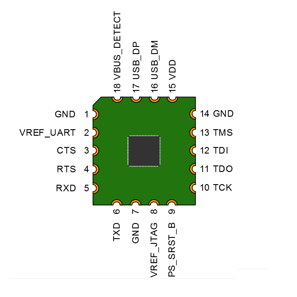
- Open drain buffer on PS_SRST_B pin allows debugging software to reset the processor core of Xilinx’s Zynq® platform
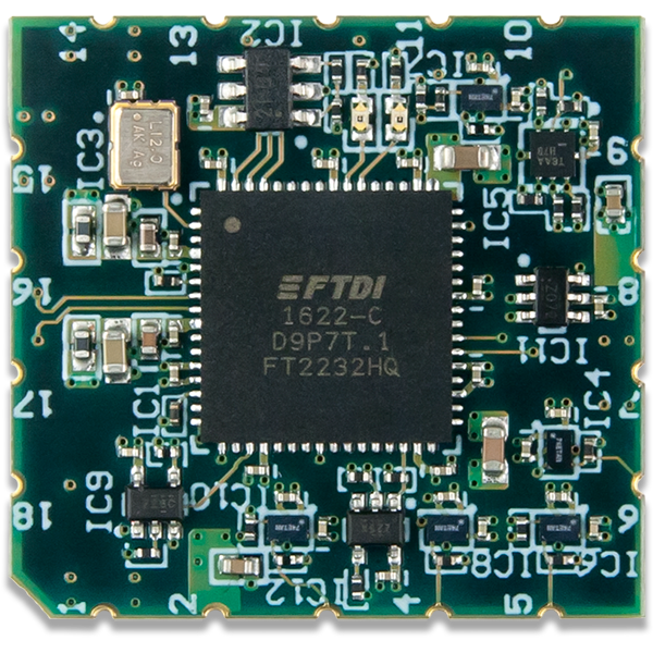
- Dual channel USB controller provides simultaneous access to both JTAG and UART interfaces
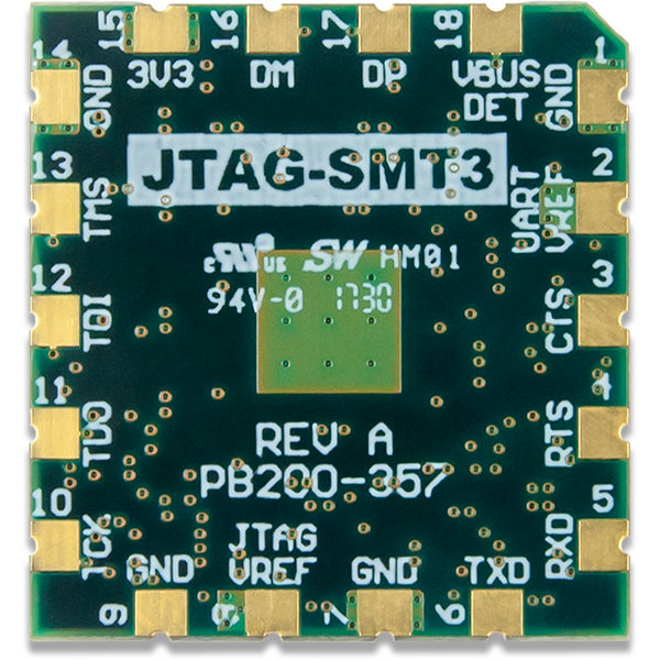
- Separate Vref for JTAG and UART signals allows each interface to operate at difference voltages (1.8V to 5.5V)
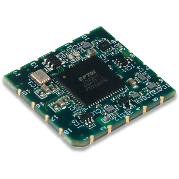
- Small form-factor surface-mount module can be directly loaded on target boards
- USB D+ and D- signals routed to pads, allowing USB connector to be placed anywhere on the host PCB
- VBUS_DETECT pin allows for reduced current consumption when the module isn’t connected to a PC
The Joint Test Action Group (JTAG)-SMT3-NC is a compact, complete, and fully self-contained surface-mount programming module for Xilinx field-programmable gate arrays (FPGAs). The module can be accessed directly from all Xilinx Tools, including iMPACT, ChipScope™, Vivado, and EDK. Users can load the module directly onto a target board and reflow it like any other component.
The JTAG-SMT3-NC uses a 3.3V main power supply and independent Vref supplies to drive the JTAG and UART signals. All JTAG signals use high speed 24mA three-state buffers that allow signal voltages from 1.8V to 5.5V, and bus speeds up to 30MBit/sec. All UART signals use high speed 24mA buffers that allow signal voltages from 1.8V to 5.5V and bus speeds up to 12Mbaud. The JTAG bus can be shared with other devices as the SMT3-NC signals are held at high impedance, except when actively driven during programming. The SMT3-NC module is CE certified and fully compliant with EU RoHS and REACH directives. The module routes the USB D+ (DP) and D- (DM) signals out to pads, providing the system designer with the ability to choose the type of USB connector and its location on the system board.