Pmod RS232 Reference Manual
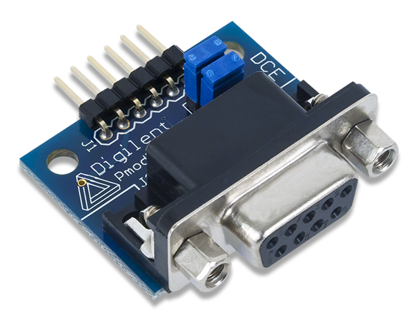
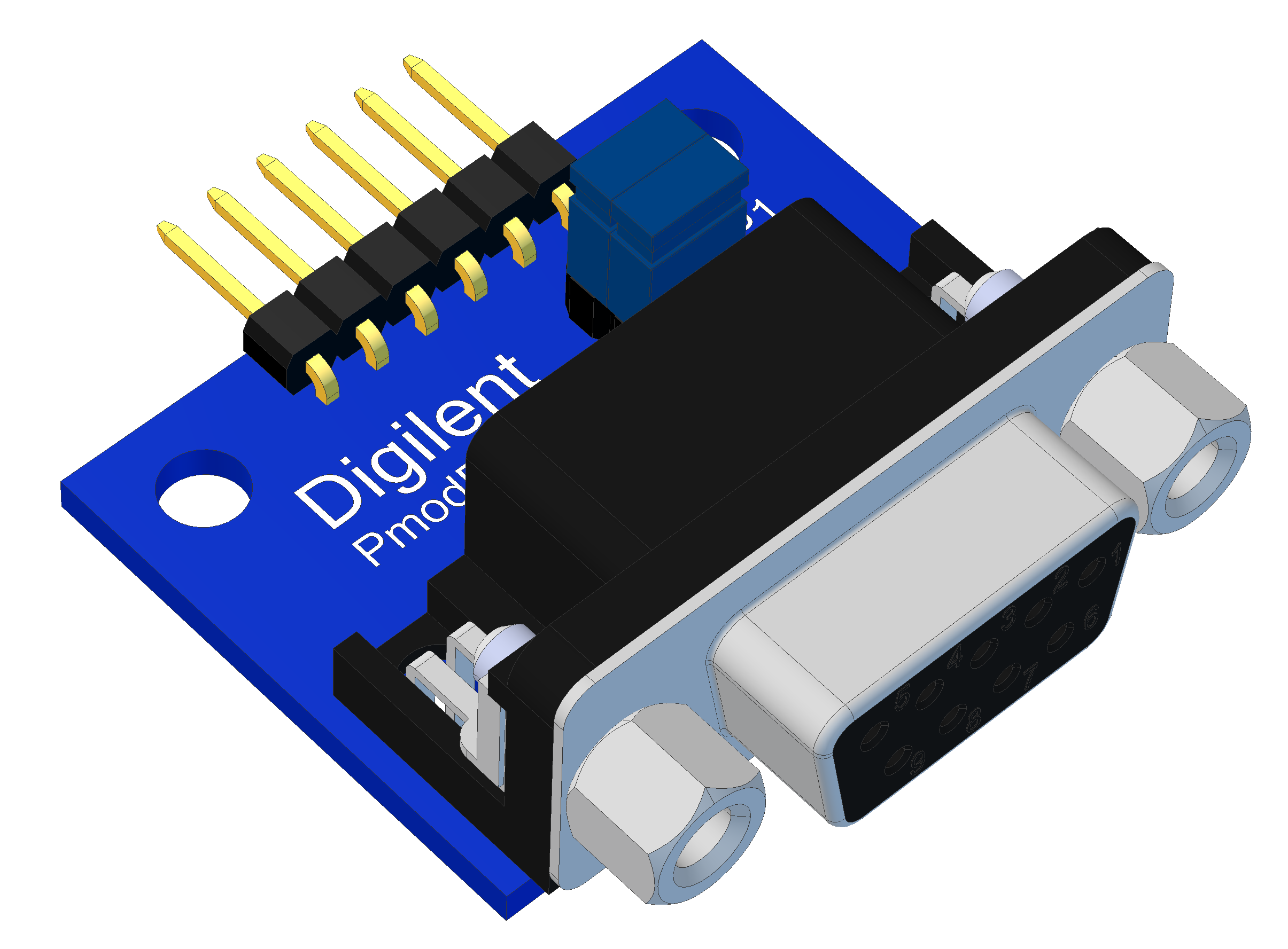
The Digilent Pmod RS232 (Revision B) converts between digital logic voltage levels to RS232 voltage levels. The RS232 module is configured as a data communications equipment (DCE) device. It connects to data terminal equipment (DTE) devices, such as the serial port on a PC, using a straight-through cable.
Download This Reference Manual
Features
- Standard RS232 DB9 connector
- Optional RTS and CTS handshaking functions
- 6-pin Pmod connector with UART interface
Functional Description
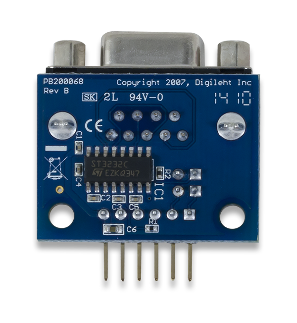
The Pmod RS232 utilizes the Maxim Integrated MAX3232 transceiver to allow the system board to communicate with UART compatible devices or other components that use a serial interface.
Interfacing with the Pmod
The Pmod RS232 communicates with the host board via the UART protocol. The arrangement of the pins is the old UART communication style (Type 3 in the Digilent Pmod Interface Specification) so that a crossover cable will be required if attaching this Pmod to one of the dedicated UART Pmod headers on any of the newer Digilent microcontroller boards. For a list of which MCU boards use the old UART protocol, see this document: connecting_uart_pmod_interfaces.pdf.
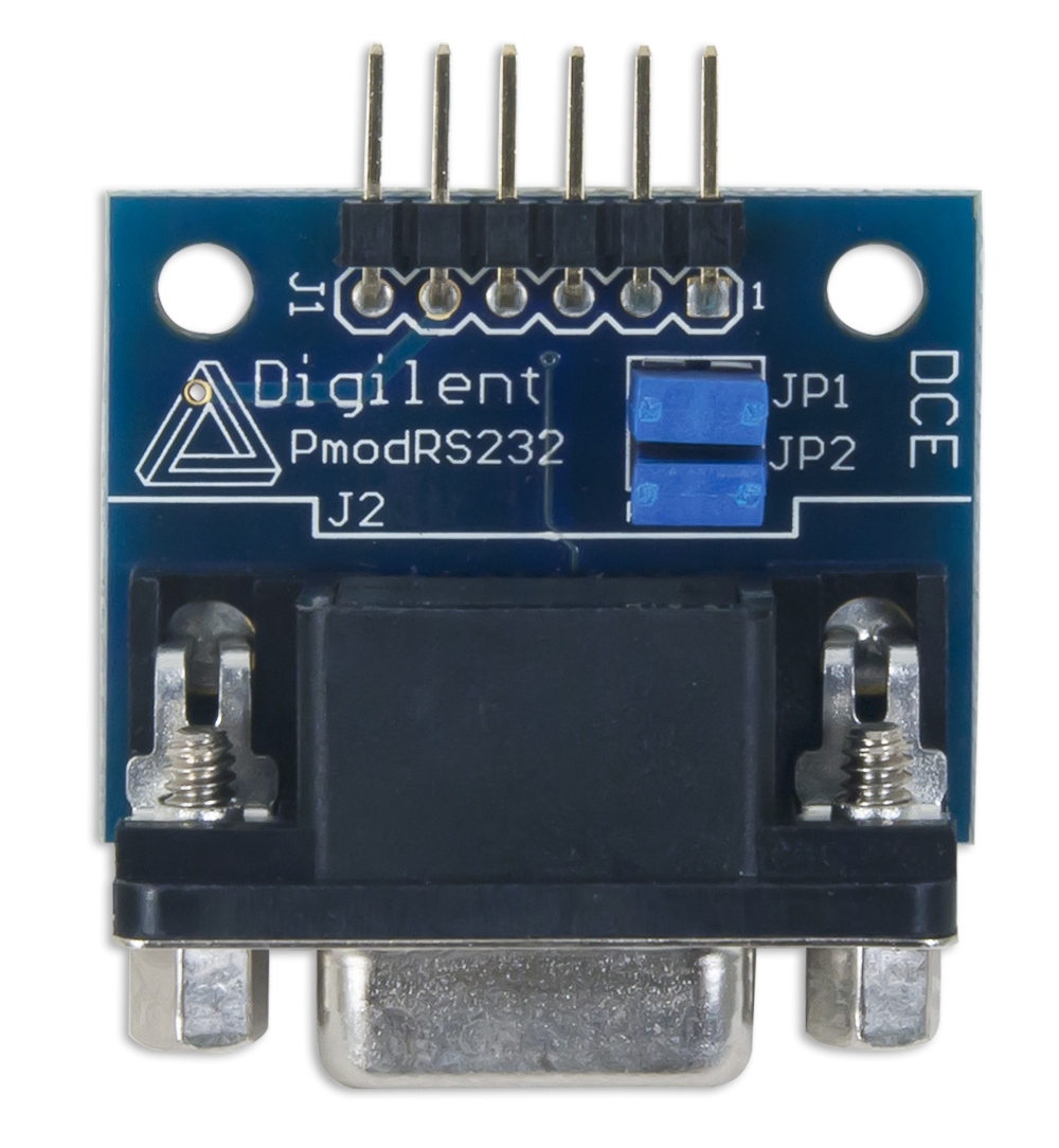
A pinout description table and diagram for the Pmod RS232 are provided below:

| Connector J1- Pin Descriptions | ||
|---|---|---|
| Pin | Signal | Description |
| 1 | CTS | Clear to Send |
| 2 | RTS | Ready to Send |
| 3 | TXD | Transmit Data |
| 4 | RXD | Receive Data |
| 5 | GND | Power Supply Ground |
| 6 | VCC | Power Supply (3.3V/5V) |
| Jumper Block Settings | ||
|---|---|---|
| JP1 | JP2 | Communication |
| Unloaded | Pins 1 and 2 are shorted together | 3-wire communication |
| Pin 1 connected to Pin 1 of JP2 and Pin 2 connected to Pin 2 of JP2 | Pin 1 connected to Pin 1 of JP1 and Pin 2 connected to Pin 2 of JP1 | 5-wire communication |
There are two jumper blocks on the Pmod RS232; JP1 and JP2. These jumper blocks allow the Pmod RS232 to communicate in either a 3-wire or 5-wire operation. When the jumper block on JP2 is loaded and the block on JP1 is unloaded, the on-board chip has its RTS and CTS lines tied together, indicating to the MAX3232 that it is free to transfer data whenever it receives any and enabling 3-wire communication. JP1 must be unloaded in this configuration to ensure that pins 1 and 2 on the Pmod header are not shorted together which could potentially damage the system board.
5-wire communication requires that pin 1 of JP1 is connected to pin 1 of JP2, and that pin 2 of both JP1 and JP2 are tied together as well, effectively allowing for CTS/RTS handshaking between the Pmod header and the on-board chip. Both the fifth wire in this configuration and the third wire in the 3-wire communication is the ground signal line.
Any external power applied to the Pmod RS232 must be within 3V and 5.5V; however, it is recommended that Pmod is operated at 3.3V.
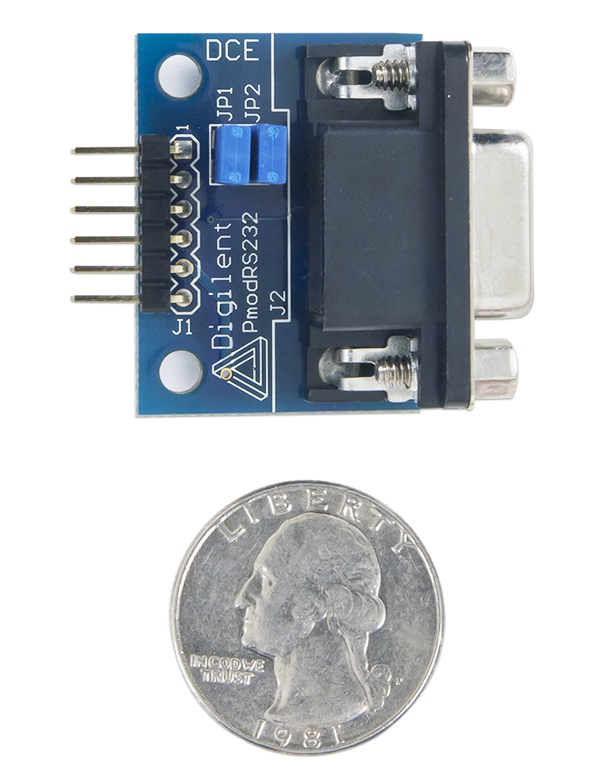
Physical Dimensions
The pins on the pin header are spaced 100 mil apart. The PCB is 1 inch long on the sides parallel to the pins on the pin header and 1.3 inches long on the sides perpendicular to the pins on the pin header. The DB9 connector adds an additional 0.25 inches to the length of the PCB that is parallel to pins on the pin header.
Additional Information
The schematics of the Pmod RS232 are available here. Additional information about on-board transceiver module can be found from its datasheet here.
Example code demonstrating how to get information from the Pmod RS232 can be found here.
If you have any questions or comments about the Pmod RS232, feel free to post them under the appropriate section (“Add-on Boards”) of the Digilent Forum.