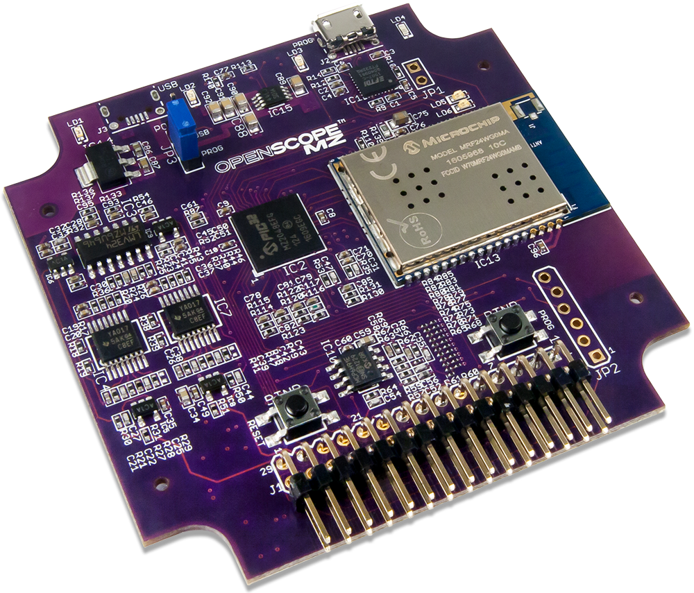
OpenScope MZ
- Wifi (802.11g)
- USB 2.0 (High Speed Required)
- PIC32MZ2048EFG124 microcontroller
- 2 External Trigger Lines
- USB powered device (B Micro)
- 4 user LEDs

Despite our hopes and effort to create an innovative and low-cost T&M solution, we’ve received consistent negative feedback on the OpenScope MZ and OpenLogger regarding overall reliability that has led us to determine that it is not up to our high standards for our test and measurement products.
Unfortunately, we are unable to fix many of the issues, so we have made the difficult decision to pull both products, and related accessories from our shelves. This will allow us to ensure we can continue to deliver on the Digilent brand promise and focus our efforts on expanding our popular and core line of Test and Measurement Products.
The materials on this page will remain here as legacy sources. Any Digilent provided support for this material will be extremely limited at best. Thank you for understanding.
OpenScope MZ is an open source, multi-function, electronic instrumentation device that can be controlled using a computer or mobile device to acquire, analyze, visualize, and generate signals from circuits, sensors, and other electronic devices. OpenScope MZ makes it easy to generate analog and digital signals using the power supply, function generator and GPIO and measure and visualize analog and digital signals using the oscilloscope and logic analyzer. Develop and debug circuits faster by generating stimuli and visualizing the response using OpenScope MZ.


Tutorials
Getting Started with the OpenScope MZ
OpenScope MZ - Update Firmware
OpenScope MZ - Instrument Panel
OpenScope MZ - Function Generator
OpenScope MZ - GPIO and Logic Analyzer
OpenScope MZ - Math and Cursors
OpenScope MZ - Offline Support