This is an old revision of the document!
Using the Impedance Analyzer
The total counteractive force to the flow of electrons through a system is known as impedance. This can be abstractly thought of as the resistance of the circuit and can be measured with an impedance analyzer. But why is a fancy tool required to measure impedance and not just a digital multimeter? The reality is that no real components, resistors, capacitors, or inductors, are purely resistive or reactive. Every component in existence is a combination of R, C, and L aspects; the unwanted aspects are called parasitics.
At low frequencies and in simple applications these parasitics can usually be safely ignored, but in high speed applications or setups with specific frequency requirements, these parasitics need to be accounted for. The Impedance Analyzer tool from Waveforms will provide a variety of information about the load under test from the impedance, admittance, inductance, capacitance, phase, and quality factor of the system. This is ideal for designing filters with tight specifications and matching impedances. It is available in the WaveForms software (version 3.6.8 or newer) for the original Analog Discovery, the Analog Discovery 2, and the Electronics Explorer board.
This tutorial will go through the available settings and controls available on the GUI and measuring a simple low pass filter. If you are using the Analog Discovery Impedance Analyzer the differences you will sense are that the reference resistances are already loaded on the board and after selecting the correct value in the software the Impedance Analyzer tool from Waveforms will take over the Oscilloscopes, WaveGen 1 and and the digital IOs in order to control the hardware
Inventory
- include link too the impedance analyzer website(Optional)
- WaveForms software (version 3.6.8 or newer is required)
- A computer with a USB port
- A load of interest to test and a resistor of a known value
Getting Started and Controls
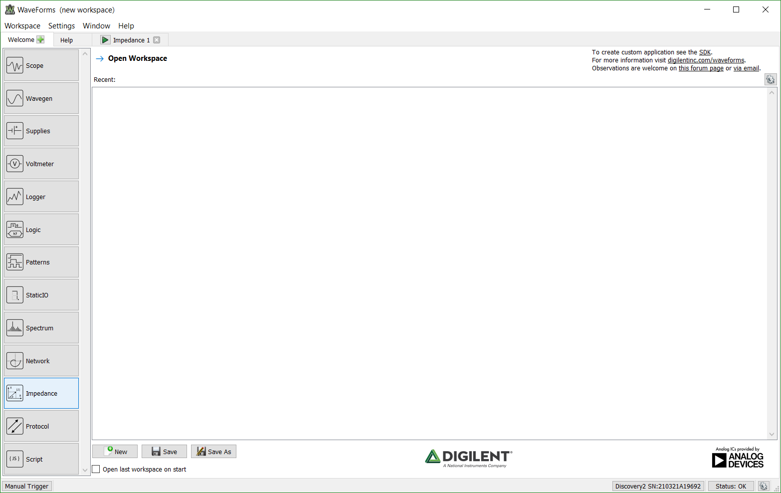
To open the Impedance Analyzer after opening up WaveForms and selecting the attached instrumentation tool, choose the Impedance tool.
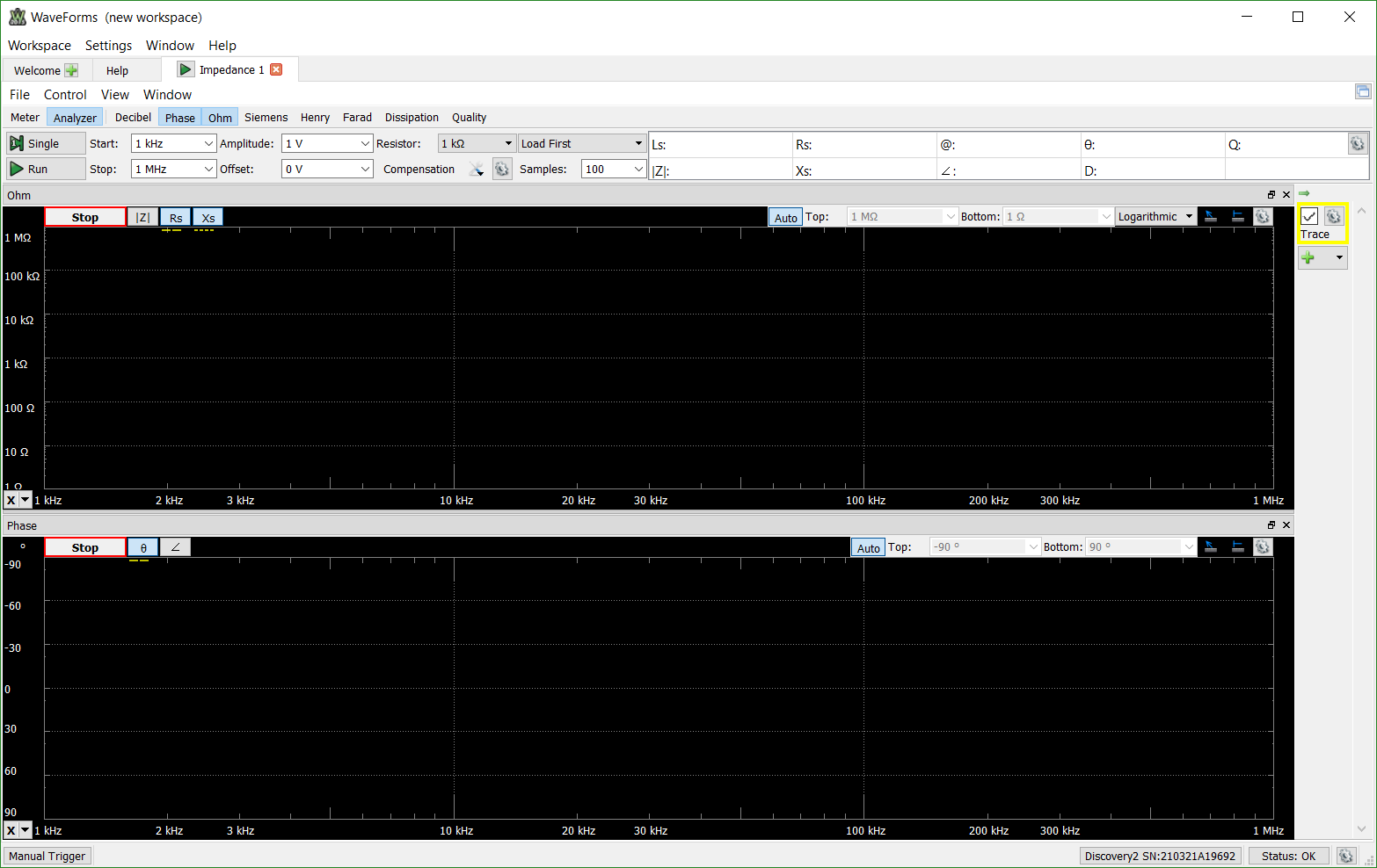
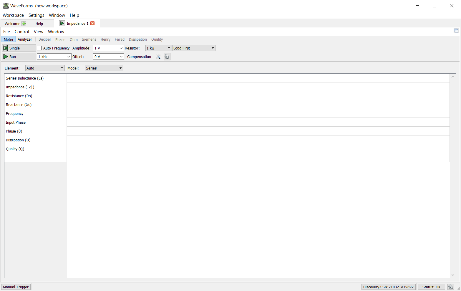
WaveForms will show the following view:
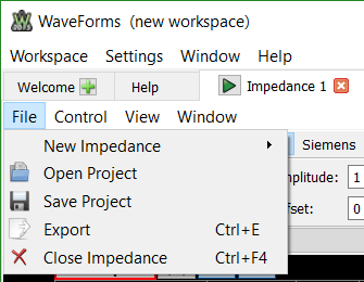
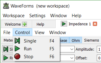
A number of options are available at the top of the GUI including File, Control, View, Window.
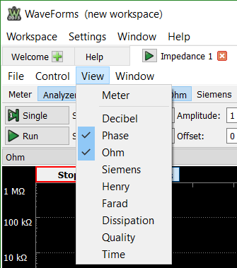
As shown in the view menu and the main toolbar, a variety of different measurements can be taken for the system. The Meter View shows all of the available measurements simultaneously but only for the calculated -3 dB of the system.
The Analyzer View shows the measured and calculated values that are toggled (highlighted blue) by the user over the specified frequency sweep. A number of the views have multiple values associated with them; for example, the Ohm view allows users to toggle and view the Impedance, Resistance, and Reactance of the system.
A number of settings to manipulate the frequency sweep are available including the start and stop frequency of the sweep, the amplitude of the applied signal, an offset to introduce bias, the number of samples to take at each frequency point, and the reference resistor used.
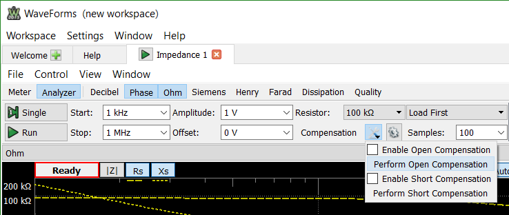
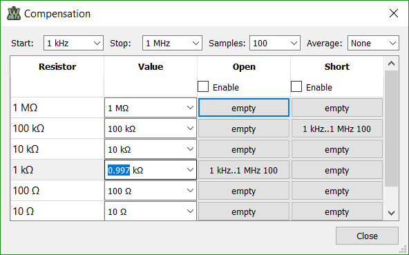
A compensation tab is also included to allow the user to enable open and short compensation and specify the exact resistor value used:
A few more settings controlling the acquisition itself are available by clicking the gear next to the Samples box to control the scale of frequency sweep, as well as offset and attenuation factors for the two oscilloscope inputs.
Setting Up the Circuit
The Impedance Analyzer tool from Waveforms accepts two different arrangements for the load of interest and the reference resistor. In both cases the first WaveForm Generator tool (WaveGen 1) as well as the positive inputs of both Oscilloscope inputs are used; the WaveForm Generator and the Oscilloscope tools will be shown as Busy when the Impedance Analyzer is in use. The two physical arrangements for the impedance analyzer are shown in the two images below:
When using the Analog Discovery impedance Analyzer you have by default the Load First arangement. For more details check the device Reference Manual
To get a clean impedance measurement, different reference resistors are recommended based on the capacitance and inductance of the load:
| Capacitance | Reference Resistor | Inductance |
|---|---|---|
| 100 pF | 1 MΩ | |
| 1 nF | 100 kΩ | |
| 10 nF | 10 kΩ | 1 μH |
| 1 μF | 10 kΩ | 1 μH |
| 10 μF | 100 Ω | 1 μH |
| 100 μF | 10 Ω | 1 mH |
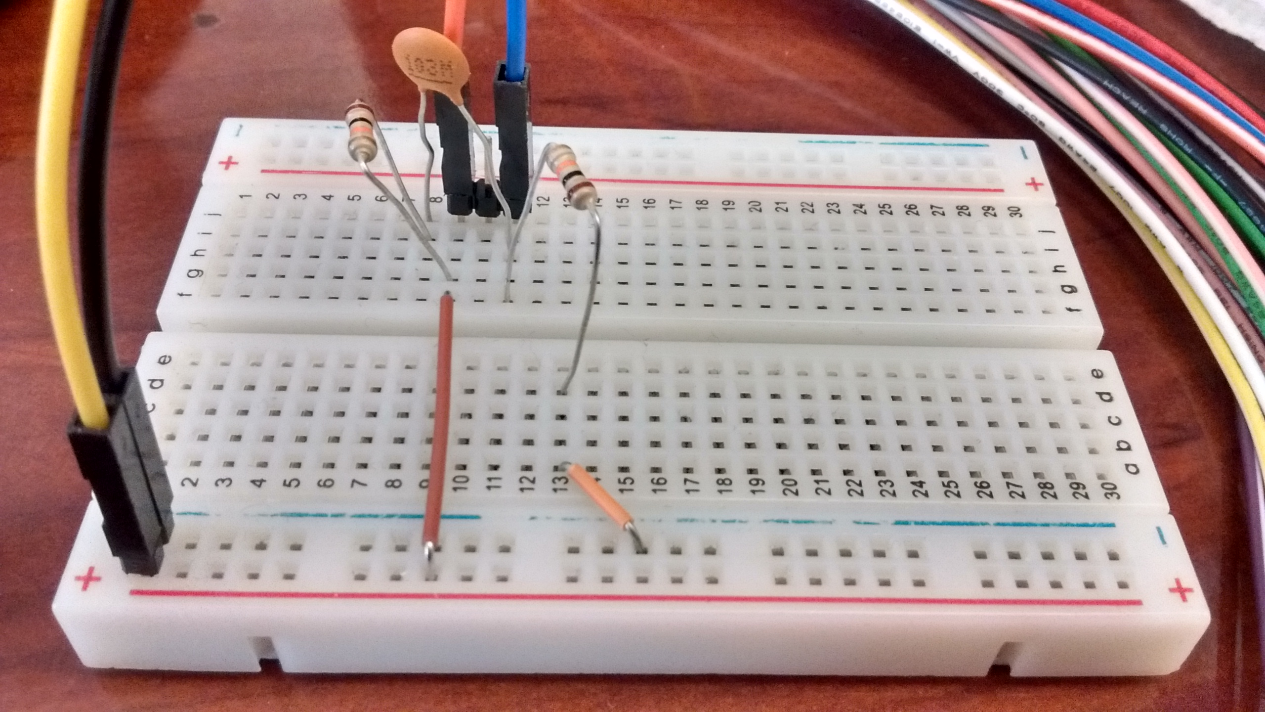
The following circuit with a low pass filter is used as an example load in this tutorial:
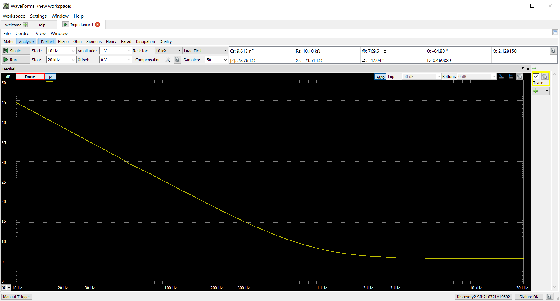
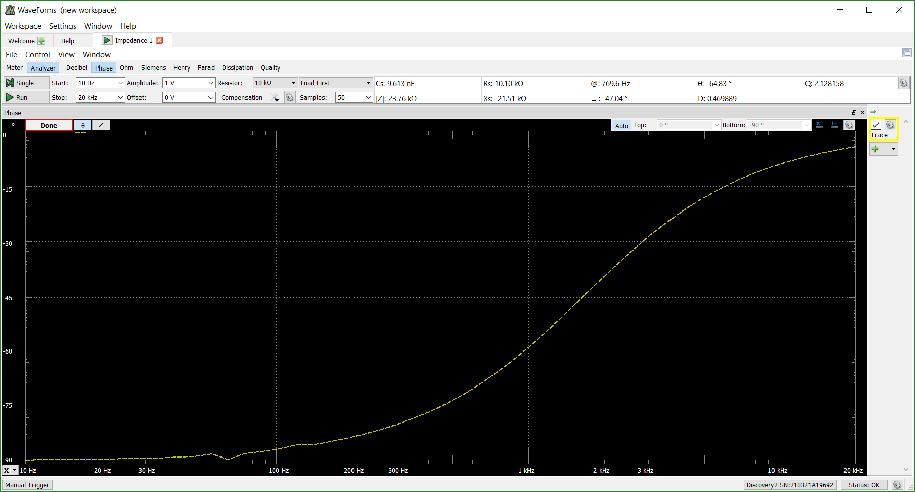
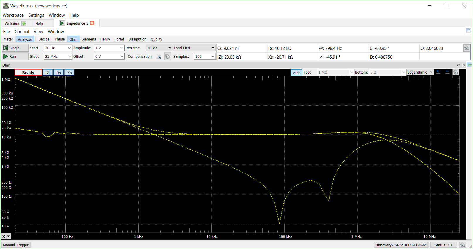
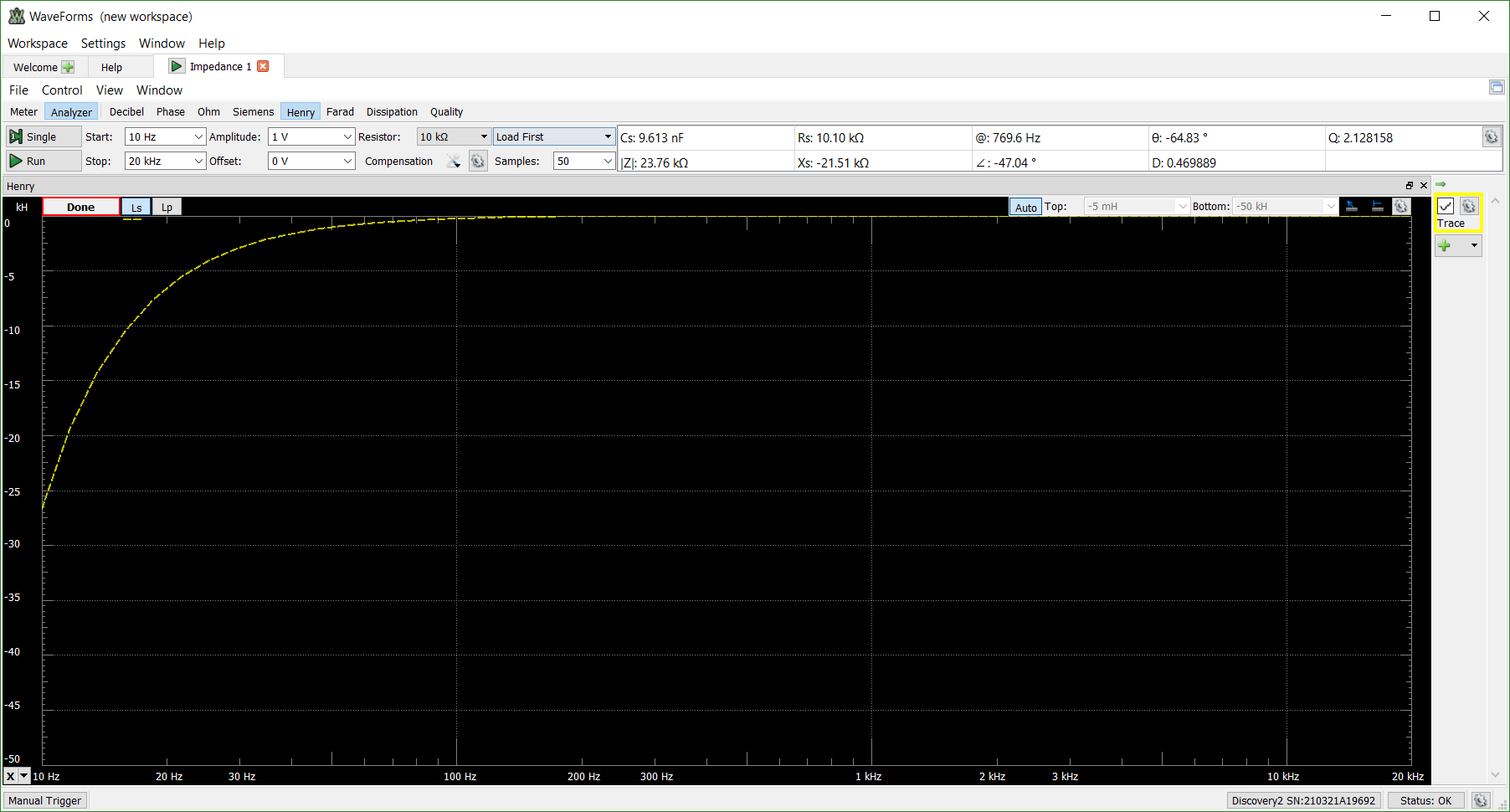
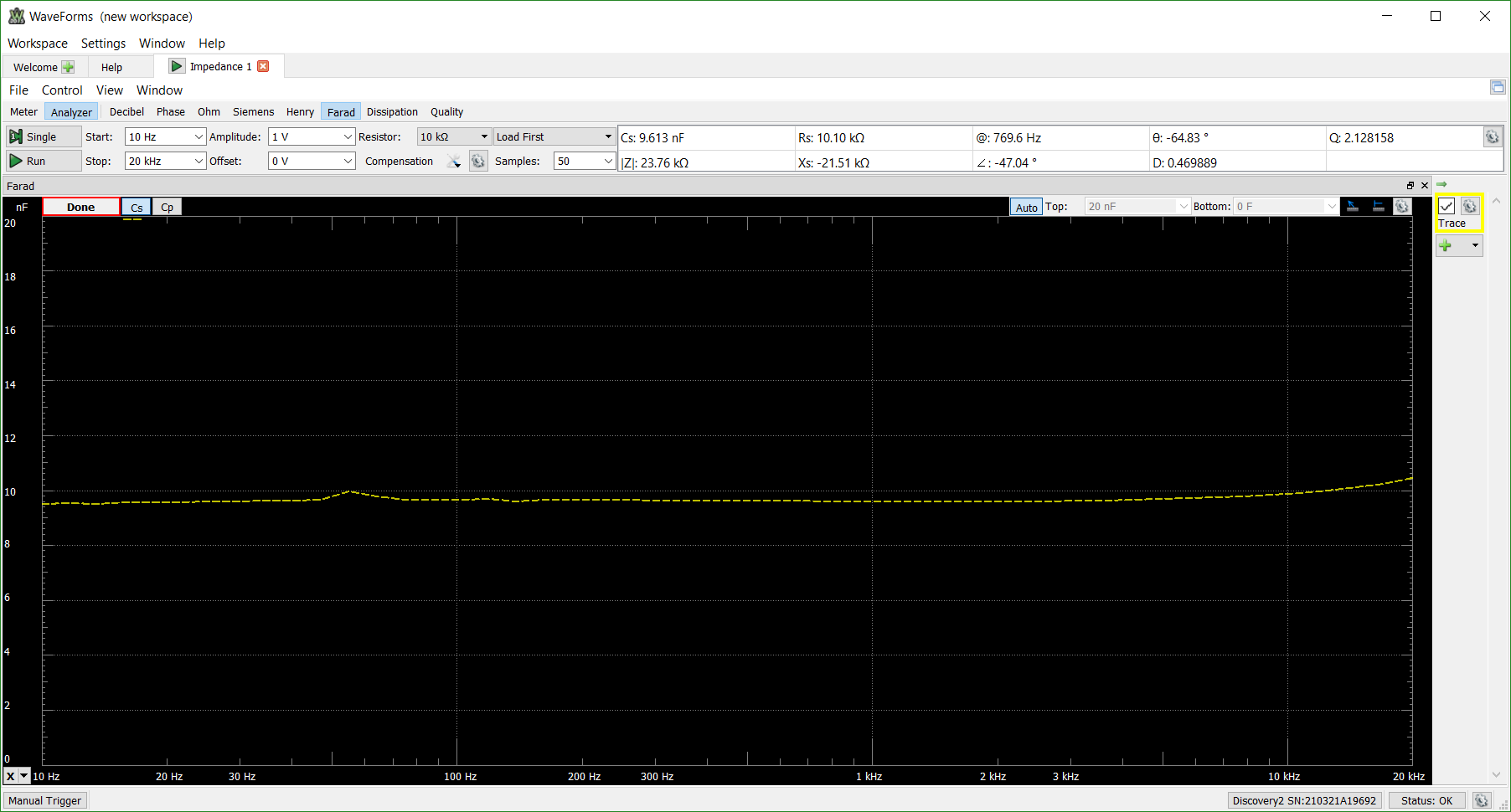
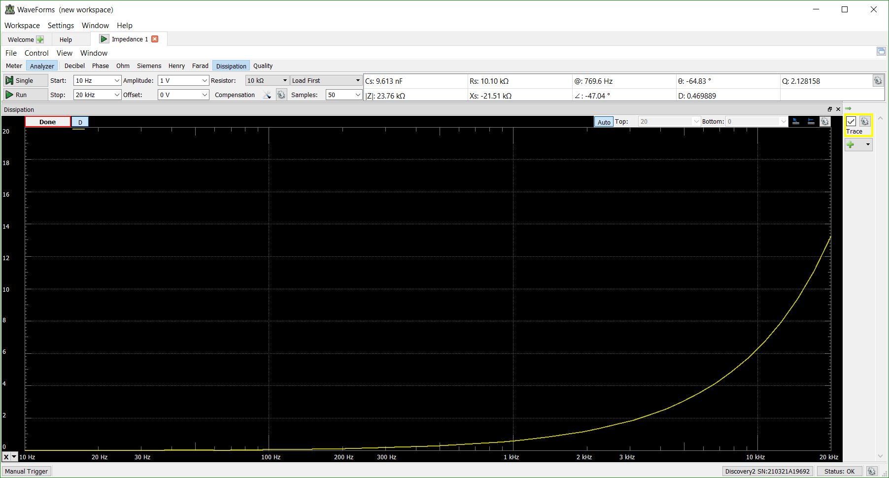
The following images show the results of analyzing the circuit from 20 Hz to 25 MHz with a 10 kΩ with a 100 samples per frequency point.
Decibel - Measures the input attenuation to the oscilloscope input
Phase - Measures the phase adjustment coming into (∠) and from (θ) the system
Ohm - Opens the Ohm view of the system including the impedance (|Z|), series resistance (Rs), and series reactance (Xs) over the frequency sweep
Siemens - Opens the Siemens view of the system including the admittance (|Y|), parallel conductance (Gp), and parallel susceptance (Bp) over the frequency range
Henry - Opens the Henry view showing the series inductance (Ls) and parallel inductance (Lp) of the system over the frequency range
Farad - Opens the Farad view to show the series capacitance (Cs) and parallel capacitance (Cp) of the system over the frequency range
Dissipation - Shows the dissipation energy ratio of real impedance to imaginary impedance
Quality - Shows the Quality view ratio of stored energy to dissipated energy
If you have any further questions about the Impedance Analyzer, please post them on the Scopes and Instruments section of the Digilent Forum.


