Lab 4a: Universal Asynchronous Receiver/Transmitter
Download This Document
1. Objectives
- Setup a terminal monitor on a PC or Linux workstation.
- Use the PIC32MX370 to send an ASCII encoded text string and display the characters on the workstation monitor.
- Receive an ASCII encoded text string from the workstation monitor and display it on the Basys MX3 LCD.
2. Basic Knowledge
3. Equipment List
3.1. Hardware
- Workstation computer running Windows 10 or higher, MAC OS, or Linux
In addition, we suggest the following instruments:
3.2. Software
The following programs must be installed on your development work station:
4. Project Takeaways
- Knowledge of a PC terminal emulation program.
- How to develop a library of PIC32 software to provide bi-directional communications of single characters and strings of characters.
- How to create a character LCD with a UART serial interface.
5. Fundamental Concepts
The Universal Asynchronous Receiver/Transmitter (UART) is an electronic device that converts parallel data to a serial data stream. Early microprocessors used independent integrated circuits to perform the conversion and frame the data stream with a start and stop bit. Currently, a vast majority of microprocessors have internal UART functionality, resulting in reduced system cost and complexity. The UART is capable of full-duplex operation, meaning simultaneously receiving and transmitting data. UARTs are generally constrained to a single peer-to-peer paired devices commonly called point-to-point communications.
Asynchronous communication is the transmission of data between two devices that are not synchronized with one another via a clocking mechanism or other technique. The term asynchronous implies the sender can initiate data transmission at any time, and the receiver must be ready to accept information when it arrives. The two devices must be operating at, or nearly equal to, the same clock frequency and are resynchronized by a START bit sent along with the data.
6. Problem Statement
Text messages will be sent to the UART serial port whenever a change in switch settings is detected and the action will be reported to a computer terminal. Whenever a text string is entered on the computer terminal, it will be displayed on the Basys MX3 LCD.
7. Background Information
Asynchronous communications is a serial data protocol that has been in use for many years. Normally eight bits of data are transmitted between handshaking characters to allow the clocks of transmitting and receiving devices to be synchronized. There are other less commonly used modes that can send 5, 6, or 7 bits of data. Each byte of data is framed by a start bit and a stop bit. A symbol is defined as a start, data, parity, or stop bit. It is common to define common to define communications speed as bits per second. The bit rate is defined as the inverse of the period of a unit symbol. Although the common standard bit rates are 50, 75, 110, 134, 150, 200, 300, 600, 1200, 1800, 2400, 4800, 9600, 19200, 38400, 57600, and 115200, communications is possible at any rate provided that the sender and receiver use the same rate. For most asynchronous communications, the term “baud” is commonly used interchangeably with the term “bit rate.”
8. Lab 4a
8.1. Requirements
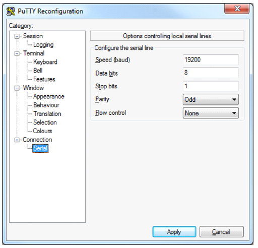
- Communications will use the PC terminal emulation program for a bit rate of 19200, odd parity, 8 data bits, and one stop bit.
- After receiving the line of text from the UART, you will clear the LCD before echoing the received string from the UART, starting at the leftmost character position on line 1 of the LCD.
- Write a C program and call it lab4a.c. This program will contain the function main and process the serial text. Put the following tasks inside the while(1) loop:
- Wait for line of text using the “getstr” function
- Clear the LCD display and home cursor
- Echo the string entered on the computer terminal to the LCD
- Sense the state for the eight slide switches and convert the switch settings to a value, where SW7 is the most significant bit. Whenever any of the switches changes state, a text message is generated using the following format:
- “b b b b b b b b 0xhh ddd\n\r” where:
- “b” is 1 or zero representing the state of SW0 through SW7 with the SW7 bit leftmost.
- “hh” is the hexadecimal value of the binary encoded switches.
- “ddd” is the decimal equivalent of the hexadecimal number generated for part b.
- “\n” is the ASCII NEW LINE control character.
- “\r” is the ASCII RETURN control character.
- Send the text string composed in requirement 5 to the UART so it will be displayed on the terminal monitor as a single line of text.
8.2. Design Phase
- Develop a data flow diagram for the software components needed for the requirements of Lab 4a.
- Schematic diagrams: Provide a block diagram of the equipment used for Lab 4a.
- Flow diagrams: Provide a complete software control flow diagram for Lab 4a.
8.3. Construction Phase
1. Connect the Basys MX3 UART USB port to one of the work station’s USB ports.
2. If the workstation is running a Windows OS, open the “Control Panel” followed by opening the “Device Manager” window. If you do not have administrator privileges, you will see the window shown in Fig. 8.1. Click on the OK box to continue. Administrative privileges are not required to view the settings.
 Figure 8.1. The device manager window showing you do not have administrator privileges.
3. Expand the tab called Ports (COM & LPT) as shown in Fig. 8.2.
 Figure 8.2. PC device manager window.
4. Note the USB Serial Port COM assignment.
5. Open the terminal emulation program on your workstation. Configure the terminal program for 19200 BAUD and ODD parity. The screen shown in Fig. A.4 of Appendix 1 is for the PuTTY terminal emulation program.
6. Launch a new Microchip MPLAB X project called LAB4b. Add the config_bits.h file to the project.
7. Develop the following UART interface functions: Note that the numeral “4” in the function names indicate that the Basys MX3 uses the PIC32MX370 UART 4. All receive functions are to be non-blocking.
uart4Init();				// 19200 Baud, ODD parity
(int) ch = uart4Getc();			// ch = -1 if no data has been received
(int) len = uart4Gets(char *str); 		// len = -1 if no data has been received
uart4Puc(char ch);<
uart4Puts(char *str);
8. Develop the PIC32 application that meets the requirements in section 8.1.
8.4. Testing
- After completing the development, run the application project to verify that the LCD is initialized correctly. I generally display an initial message on the LCD for one second that declares the LCD is functional.
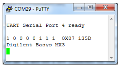
- Toggle the slide switches to verify that the terminal screen displays text similar to Figure A.3.
- Enter a series of text strings that verify the following operations:
- A text string containing between 1 and 16 characters displays only on the first LCD line.
- A text string containing between 17 and 32 characters displays on both the first and second LCD lines as shown in Fig. A.2.
- A text string containing between 17 and 32 characters displays on both the first and second as well as wrapping back around to the first LCD line.
- Connect the Analog Discovery 2 to the Basys MX3 board.
- Configure the Logic window to display signals DIO 8 which is the UART RX pin. Measure the time from the beginning of the start character to the beginning of the stop character.
- Configure the Logic window to display signals DIO 0 through DIO 3. Label the signals as follows:
- DIO 0 DB0
- DIO 1 EN
- DIO 2 RW
- DIO 3 RS
- Capture a single character display as shown in Fig. 8.3.
- Measure the time the LCD reported being busy.
- Measure the time required to output a single character.
- Measure the time required to display a string of 20 characters.
 Figure 8.3. Handshaking pins and data bit zero for single character write to the LCD.
9. Questions
1. What is the effective data rate of the UART? (Remember to include the period of the stop signal that cannot be measured in testing step 4a.)
2. Based on the data collected in step 4 parts 4.4 and 4.5 of the testing procedure, what is the effective character display rate in characters per second?
3. Based on the data collected in step 4 part 4.6, how much does moving the cursor from line 1 to line 2 slow down the LCD character display rate? Justify your answer.
10. References
- PIC32MX330/350/370/430/450/470 Family Data Sheet
- “Using the USART in Asynchronous Mode”, http://ww1.microchip.com/downloads/en/DeviceDoc/usart.pdf
- “Asynchronous Communications with the PICmicro® USART”, http://ww1.microchip.com/downloads/en/AppNotes/00774a.pdf
- HD44780U LCD data sheet, https://www.sparkfun.com/datasheets/LCD/HD44780.pdf
Appendix A: Basys MX3 Schematic Drawings
 Figure A.1. PIC32MX370 to FT232RQR IC schematic diagram.
 Figure A.2. UART USB connector on the Basys MX3.
 Figure A.3. PuTTy screen shot generating LCD display.
 Figure A.4. PuTTY screen shot of serial configuration for 19200 BAUD and ODD parity.
Appendix B: Allocating a Heap in MPLAB X
If when compiling your project you see an error like “ld.exe Error: A heap is required, but has not been specified,” this is because you need to specify a heap size by setting “Run” →“Set Project Configuration” → “Customize…”. Go to the “xc32-ld” category (under “XC32 (Global Options)”) → “Heap size (bytes)” to “0” The configuration window should look like Fig. B.1. Click on the “Apply” button followed by clicking on the “OK” button. See http://microchip.wikidot.com/mplabx:creating-a-heap.
 Figure B.1. Allocating Heap size.
