Using the Analog Discovery 2 to Debug Different Motor Controllers
The Analog Discovery 2 is a useful tool for debugging projects or designs that use a variety of signal types and can be used with the WaveForms SDK to write automated or custom tests. The following example is a replication of a motor controller tester application used by a customer working in consumer electronics. In this particular application multiple motors were used in a system where their functionality directly impacted the safety of the user, so extensive testing was necessary.
As an example of what was done the following guide presents how to create a C/C++ project for the Analog Discovery 2 using WaveForms SDK and how to use it to debug an H-Bridge DC motor controller and a stepper motor controller, both used in an automatic baby swing design.
Prerequisites
Hardware
Software
- Visual Studio Code, or any other editor of your choice
- C/C++ compiler (this might be included in your IDE)
Note: WaveForms can be installed by following the WaveForms Getting Started Guide. By installing WaveForms, WaveForms SDK will be installed, which is needed later in this guide.
Preparation
In the following, an existing Arduino motor controller project will be tested and debugged. The project consists of a brushed DC and a stepper motor, with the proper drivers, two potentiometers and a latching hall-effect sensor, all controlled by an Arduino microcontroller. One potentiometer sets the speed of the DC motor and the other sets the position of the stepper (like in the AccelStepper - ProportionalControl example). The Hall-effect sensor changes the DC motor's direction on every rising/falling edge. The simplified design of the device, the schematic and the Arduino code can be downloaded from here.
Creating this motor controller project is beyond the scope of this guide, and the testing concepts covered here can be used in a wide variety of projects. To try out this example, you can connect the Analog Discovery 2 to any simple motor driving application, or with some modification debug your own projects using the code snippets discussed below.
Hardware Setup
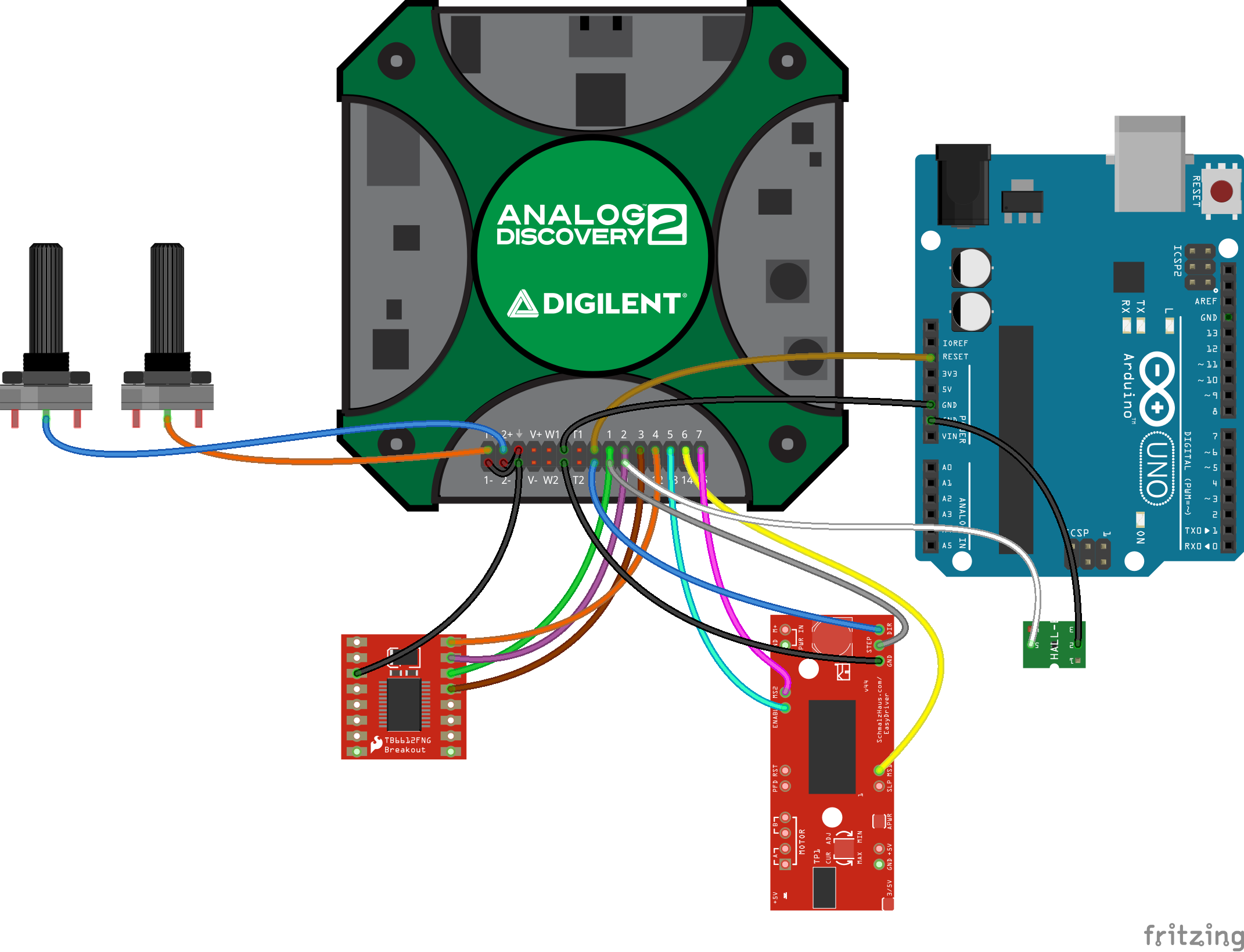
In the project we want to debug as an example, an H-Bridge DC motor driver and a stepper driver are controlled by an Arduino UNO, according to the input of two potentiometers. One potentiometer sets the speed of the DC motor, while the other sets the position of the stepper. A Hall-effect sensor sends an interrupt signal to the MCU after every half-turn of the DC motor, and the direction of rotation is changed.
In order to test the system first the potentiometer values should be measured, then both motors should be tested by sending digital control signals to the drivers, while the MCU is disabled, then, after enabling the MCU again, it's output signals should be recorded.
To read the voltages on the potentiometers, the two analog input channels will be used. To control the motor drivers and to read the MCU output signals, digital I/O lines will be used. The image to the right shows an example of how this all can be wired up.
Note: Any digital I/O line can be connected to any pin of the MCU/drivers, just take a note of the connections, as they have to be defined later in the code.
Note: The wiring diagram only shows the connections between the Analog Discovery 2 and the other devices.
Creating the Project
When the C/C++ project is created, copy the dwf.lib file from the WaveForms installation library, WaveFormsSDK\lib\x86 subfolder and the dwf.h file from the WaveForms installation library, WaveFormsSDK\inc subfolder to your project directory. Include the dwf.h header file in your source file, and link the dwf.lib library into the project. Following this, you can use the functions from the WaveForms SDK.
Functions for Controlling Different Instruments
In the following, the functions used for controlling the instruments in this example are discussed. For details about other available functions in the WaveForms SDK, check the WaveForms SDK Reference Manual.
- Connecting and Disconnecting the Analog Discovery 2
-
To be able to use the Analog Discovery 2, it must be connected. To safely connect the device, the program should check if there is an Analog Discovery 2 connected to the PC. If yes, it also should check, whether there are any devices, which are available (unused by other programs). If an available device is detected, it should be opened, so its device handle (hdwf) can be passed to the other functions.
//initialization function for AD2
bool init_AD2(HDWF *hdwf, char *error)
{
    // detect if AD2 is connected or not
    int nr_of_connected_dev;
    FDwfEnum(devidDiscovery2, &nr_of_connected_dev);
    if (nr_of_connected_dev == 0)
    {
        strcpy(error, "Error: Analog Discovery 2 is not connected");
        error[strlen("Error: Analog Discovery 2 is not connected")] = 0;
        return false;
    }

    // detect if AD2 is used by other program or not (select the unused one if there are more devices)
    int unused_dev_index = -1;
    for (int i = 0; i < nr_of_connected_dev; i++)
    {
        int device_is_used;
        FDwfEnumDeviceIsOpened(i, &device_is_used);
        if (!device_is_used)
        {
            unused_dev_index = i; //save free device index
            break;
        }
    }
    if (unused_dev_index == -1)
    {
        strcpy(error, "Error: all connected Analog Discovery 2s are in use");
        error[strlen("Error: all connected Analog Discovery 2s are in use")] = 0;
        return false;
    }

    // connect to the unused AD2
    if (!FDwfDeviceOpen(unused_dev_index, hdwf))
    {
        strcpy(error, "Error: can't connect to Analog Discovery 2");
        error[strlen("Error: can't connect to Analog Discovery 2")] = 0;
        return false;
    }
    return true;
}
When the program finishes using the Analog Discovery 2, it must disconnect it, not to prevent other software from using it. Before disconnecting, all used instruments should be reset to their default state with the respective Reset function.
//reset every used instrument and close device
void close_AD2(HDWF *hdwf)
{
    FDwfDigitalIOReset(*hdwf);  //reset digital i/o
    FDwfAnalogInReset(*hdwf);   //reset analog in
    FDwfDigitalOutReset(*hdwf); //reset digital out
    FDwfDigitalInReset(*hdwf);  //reset digital in
    FDwfDeviceClose(*hdwf);     //close device
    return;
}
- Static I/O
-
To control the state of the Analog Discovery 2's digital I/O pins, the FDwfDigitalIO functions will be used. The function should be similar to the digitalWrite() function on Arduino: it receives the number of the pin and a logic state, and sets the received state on the given digital I/O line.
The first step is, to get the pins, which are set as output, and the states set on these pins. The function should not modify the state of the other pins, only the given one. In the next step, a mask is applied to the variable containing the pins used as a digital output, as well as on the variable containing the states of the output pins. The new values are sent back to the Analog Discovery 2.
//write a value on a specific digital i/o pin
void digital_write(HDWF *hdwf, int pin, int value)
{
    // get current state
    unsigned int previous_mask, previous_value;
    FDwfDigitalIOOutputEnableGet(*hdwf, &previous_mask); //get current pin setup
    FDwfDigitalIOInputStatus(*hdwf, &previous_value);    //get current pin state

    //set new mask
    unsigned int power = 1; //power = 2^pin
    for (int i = 0; i < pin; i++)
    {
        power *= 2;
    }
    previous_mask |= power;

    //set new state
    if (value != 0)
    {
        previous_value |= power;
    }
    else
    {
        previous_value &= ~power;
    }

    //output new values
    FDwfDigitalIOOutputEnableSet(*hdwf, previous_mask); //set pin setup
    FDwfDigitalIOOutputSet(*hdwf, previous_value);      //set pin state
    return;
}
- Voltmeter
-
To read voltages with the Analog Discovery 2, the FDwfAnalogIn functions will be used. The function should be similar to the analogRead() function on Arduino, with some modifications: the function receives the used oscilloscope channel and, optionally, the number of samples to average.
Firstly, the channel, the range, and the offset are set, then triggering is disabled, then samples are acquired and averaged, if necessary.
//read voltage on a given analog channel
float analog_read(HDWF *hdwf, int channel, int average)
{
    //configure the oscilloscope
    channel--;                                          //channels start from 0
    FDwfAnalogInChannelEnableSet(*hdwf, channel, true); //channel is enabled
    FDwfAnalogInChannelRangeSet(*hdwf, channel, -6);    //a range of -6 to 6 volts
    FDwfAnalogInChannelOffsetSet(*hdwf, channel, 0);    //offset is 0V
    FDwfAnalogInConfigure(*hdwf, false, false);         //no auto trigger
    Wait(2000);                                         //wait 2 seconds

    //average samples
    float sum = 0;
    for (int i = 0; i < average; i++)
    {
        FDwfAnalogInStatus(*hdwf, false, NULL); //wait for acquisition
        double temporal_voltage;
        FDwfAnalogInStatusSample(*hdwf, channel, &temporal_voltage); //sample acquisition
        sum += temporal_voltage;
        Wait(100);
    }
    sum /= average; //calculate average
    return sum;
}
- Logic Analyzer
-
To acquire digital data with the Analog Discovery 2, the FDwfDigitalIn functions will be used. The function should be able to save a defined number of samples in a matrix, where every column represents a digital input line. The function should also be able to signal the loss or corruption of data if that's the case.
As a start, the Static I/O, the Logic Analyzer, and the Pattern Generator instruments should be reset to their default state. Following this, the acquisition sample rate and the output data format should be set. When using Analog Discovery 2, the recommended data format is 16 bits per word, as the device has 16 digital I/O lines.
The acquisition should be triggered by a rising or falling edge on any pin, but it also should have a timeout, to record cases when there are no changes in the signal (can be useful when debugging).
After starting the instrument, data is recorded in a buffer continuously. In a loop, this buffer is continuously saved to an output array, while it is also checked, if there are any corrupt, or lost data words. If the desired sample count is achieved, the loop is exited.
Finally, the recorded data is formatted and the possible errors retuned.
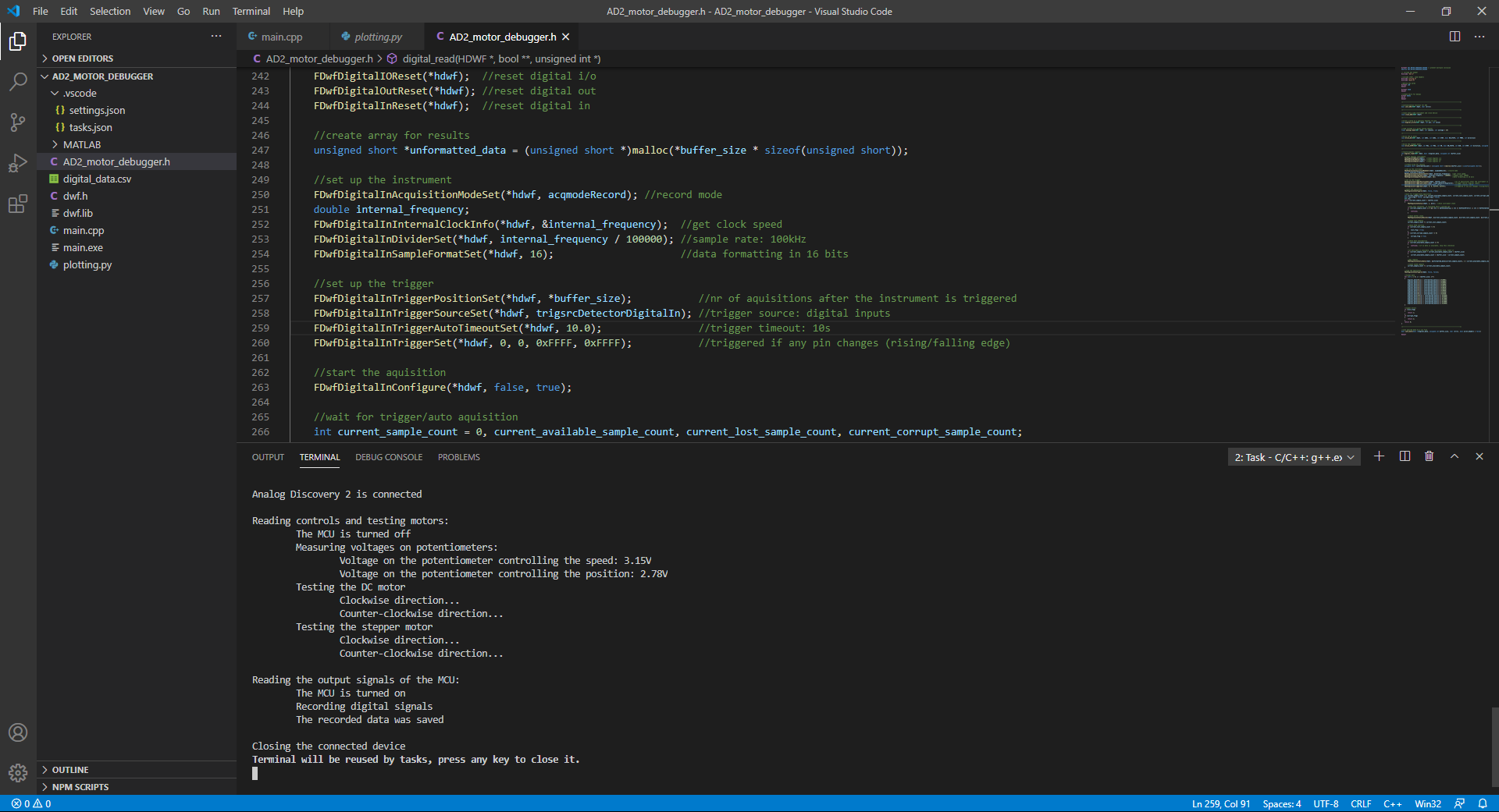
//record digital signals int digital_read(HDWF *hdwf, bool **digital_data, unsigned int *buffer_size) { //reset digital instruments FDwfDigitalIOReset(*hdwf); //reset digital i/o FDwfDigitalOutReset(*hdwf); //reset digital out FDwfDigitalInReset(*hdwf); //reset digital in //create array for results unsigned short *unformatted_data = (unsigned short *)malloc(*buffer_size * sizeof(unsigned short)); //set up the instrument FDwfDigitalInAcquisitionModeSet(*hdwf, acqmodeRecord); //record mode double internal_frequency; FDwfDigitalInInternalClockInfo(*hdwf, &internal_frequency); //get clock speed FDwfDigitalInDividerSet(*hdwf, internal_frequency / 100000); //sample rate: 100kHz FDwfDigitalInSampleFormatSet(*hdwf, 16); //data formatting in 16 bits //set up the trigger FDwfDigitalInTriggerPositionSet(*hdwf, *buffer_size); //nr of aquisitions after the instrument is triggered FDwfDigitalInTriggerSourceSet(*hdwf, trigsrcDetectorDigitalIn); //trigger source: digital inputs FDwfDigitalInTriggerAutoTimeoutSet(*hdwf, 10.0); //trigger timeout: 10s FDwfDigitalInTriggerSet(*hdwf, 0, 0, 0xFFFF, 0xFFFF); //triggered if any pin changes (rising/falling edge) //start the aquisition FDwfDigitalInConfigure(*hdwf, false, true); //wait for trigger/auto aquisition int current_sample_count = 0, current_available_sample_count, current_lost_sample_count, current_corrupt_sample_count; bool lost_flag = false, corrupt_flag = false; STS sts; while (current_sample_count < *buffer_size) { FDwfDigitalInStatus(*hdwf, 1, &sts); //check instrument state //skip this iteration, if recording hasn't started yet if (current_sample_count == 0 && (sts == DwfStateConfig || sts == DwfStatePrefill || sts == DwfStateArmed)) { continue; } //check buffer state FDwfDigitalInStatusRecord(*hdwf, ¤t_available_sample_count, ¤t_lost_sample_count, ¤t_corrupt_sample_count); //count lost samples current_sample_count += current_lost_sample_count; //check FIFO overflow if (current_lost_sample_count != 0) { lost_flag = true; } if (current_corrupt_sample_count != 0) { corrupt_flag = true; } //check data availability if (current_available_sample_count == 0) { continue; //if no data is available, skip this iteration } //if more data is available, then the buffer size, limit it if (current_sample_count + current_available_sample_count > *buffer_size) { current_available_sample_count = *buffer_size - current_sample_count; } //get samples FDwfDigitalInStatusData(*hdwf, &unformatted_data[current_sample_count], 2 * current_available_sample_count); //count saved samples current_sample_count += current_available_sample_count; } //stop the aquisition FDwfDigitalInConfigure(*hdwf, false, false); //format data for (int i = 0; i < *buffer_size; i++) { digital_data[0][i] = unformatted_data[i] & 0x0001; digital_data[1][i] = unformatted_data[i] & 0x0002; digital_data[2][i] = unformatted_data[i] & 0x0004; digital_data[3][i] = unformatted_data[i] & 0x0008; digital_data[4][i] = unformatted_data[i] & 0x0010; digital_data[5][i] = unformatted_data[i] & 0x0020; digital_data[6][i] = unformatted_data[i] & 0x0040; digital_data[7][i] = unformatted_data[i] & 0x0080; digital_data[8][i] = unformatted_data[i] & 0x0100; digital_data[9][i] = unformatted_data[i] & 0x0200; digital_data[10][i] = unformatted_data[i] & 0x0400; digital_data[11][i] = unformatted_data[i] & 0x0800; digital_data[12][i] = unformatted_data[i] & 0x1000; digital_data[13][i] = unformatted_data[i] & 0x2000; digital_data[14][i] = unformatted_data[i] & 0x4000; digital_data[15][i] = unformatted_data[i] & 0x8000; } //signal errors if (lost_flag) { return 1; } if (corrupt_flag) { return 2; } return 0; }
- Pattern Generator
-
To generate a PWM signal with a given duty cycle, the FDwfDigitalOut functions will be used. First, the frequency of the pattern generator on the selected digital I/O line should be enabled, then the signal frequency should be set. The duty cycle is given as high time and low time.
The following code snippet initializes a PWM signal on the digital I/O line CH and gradually increases its duty cycle from 0% to 100%, with 1% increase after every 50ms, then stops the signal.
//set up the pwm signal
FDwfDigitalOutEnableSet(*hdwf, CH, true); //enable channel
FDwfDigitalOutTypeSet(*hdwf, CH, 0);      //set type to previous_value
double internal_clock_frequency;
FDwfDigitalOutInternalClockInfo(*hdwf, &internal_clock_frequency); //get clock frequency
unsigned int range_min, range_max;
FDwfDigitalOutCounterInfo(*hdwf, CH, &range_min, &range_max); //get counter range
int frequency = 1000;                                           //1KHz pwm frequency
unsigned int divider = ceil(internal_clock_frequency / frequency / range_max);
FDwfDigitalOutDividerSet(*hdwf, CH, divider); //set pwm frequency
unsigned int pulse = round(internal_clock_frequency / frequency / divider);

//varying the speed of the motor
for (int i = 0; i < 100; i++)
{
    unsigned int max = pulse * i / 100;
    unsigned int min = pulse - max;
    FDwfDigitalOutCounterSet(*hdwf, CH, min, max); //set duty cycle
    FDwfDigitalOutConfigure(*hdwf, true);            //start the instrument
    Wait(50);
}

//stop the motor
FDwfDigitalOutEnableSet(*hdwf, CH, false);
The Complete Program
The complete source code can be downloaded from here: ad2_motor_debugger_v2.zip. It contains the dwf.h header file, the dwf.lib library, the AD2_motor_debugger.h header, which contains the functions for different operations, the main.cpp source file, which is a wrapper, defines the structure of the project and two scripts, one in Python and one in MATLAB, for displaying the recorded data.
At the beginning of the project, the connections should be defined. By defining these at the start of the code, it is easier to modify them, if the wiring of the debugger to the MCU, or to the motor drivers is changed. The default state of the motor driver enable pins and the used libraries are also defined here.
//define connections
//digital i/o
#define MCU_RESET 0
#define DC_AIN1 1
#define DC_AIN2 2
#define DC_STBY 3
#define DC_PWMA 4
#define STEP_EN 5
#define STEP_MS1 6
#define STEP_MS2 7
#define STEP_DIR 8
#define STEP_STEP 9
#define HALL 10
//analog in
#define POT_SPEED 1
#define POT_POS 2

//define defaults
#define DC_ON HIGH  //state of the stby pin when the motor is on
#define STEP_ON LOW //state of the en pin when the stepper is on

//define constants
#define TEST_ANALOG_INPUT_AVERAGE 10 //how many measurements should be averaged
#define TEST_STEPS 1024              //how many steps to do with the stepper motor
#define OUTPUT_CSV_HEADERS false     //save headers to the output csv file or not

/*-------------------------------------------------------------------------*/

//include headers needed for input/output
#include <stdio.h>
#include <stdlib.h>
#include <stdbool.h>
#include <conio.h>

//include the DWF header and the custom header for this project
#include "dwf.h"
#include "AD2_motor_debugger.h"
In the main function, the first step is to connect the Analog Discovery 2. If it can't be connected, the program must be finished, as the rest of the functions can't be called. The function init_AD2() is discussed under the Functions for Controlling Different Instruments heading, in the Connecting and Disconnecting the Analog Discovery 2 drop-down.
//main function
int main(int argc, char **argv)
{
    HDWF hdwf;       //variable for instrument handle
    char error[512]; //variable for error messages

    // initialize the Analog Discovery 2
    if (!init_AD2(&hdwf, error))
    {
        printf("%s\nPress any key to exit...", error);
        _getch();
        return 0;
    }
    printf("Analog Discovery 2 is connected\n");
    Wait(2000); //wait 2 seconds
To test the motor drivers, the microcontroller must be turned off by setting it's RESET pin to low. After that, the voltages on the potentiometers can be read, and the digital_write() and PWM generation functions can be used to test both motors with varying speeds, in both directions. Details about the used functions can be found under the Functions for Controlling Different Instruments heading, in the Voltmeter, Static I/O and Pattern Generator drop-downs.
//main function
printf("\nReading controls and testing motors:\n");

// turn the microcontroller off to read/test peripherals
printf("\tThe MCU is turned off\n");
digital_write(&hdwf, MCU_RESET, LOW);

//read voltages on potentiometers
printf("\tMeasuring voltages on potentiometers:\n");
float voltage_speed = analog_read(&hdwf, POT_SPEED, TEST_ANALOG_INPUT_AVERAGE);
printf("\t\tVoltage on the potentiometer controlling the speed: %2.2fV\n", voltage_speed);
float voltage_position = analog_read(&hdwf, POT_POS, TEST_ANALOG_INPUT_AVERAGE);
printf("\t\tVoltage on the potentiometer controlling the position: %2.2fV\n", voltage_position);

//testing the DC motor
printf("\tTesting the DC motor\n\t\tClockwise direction...\n");
drive_DC(&hdwf, DC_AIN1, DC_AIN2, DC_STBY, DC_ON, DC_PWMA, 1);
printf("\t\tCounter-clockwise direction...\n");
drive_DC(&hdwf, DC_AIN1, DC_AIN2, DC_STBY, DC_ON, DC_PWMA, 0);

//testing the stepper
printf("\tTesting the stepper motor\n\t\tClockwise direction...\n");
drive_STEP(&hdwf, STEP_MS1, STEP_MS2, STEP_EN, STEP_ON, STEP_DIR, STEP_STEP, 1, TEST_STEPS);
printf("\t\tCounter-clockwise direction...\n");
drive_STEP(&hdwf, STEP_MS1, STEP_MS2, STEP_EN, STEP_ON, STEP_DIR, STEP_STEP, 0, TEST_STEPS);
To record the signals coming from the MCU, it must be turned on, by setting its RESET pin to logic high. After this, the number of samples to record must be specified (data_size), and a matrix with the proper size (digital_data) must be created before recording the data. After the acquisition, data loss/corruption should be checked, then the recordings should be saved in a file. Details about the digital_read() function can be found under the Functions for Controlling Different Instruments heading, in the Logic Analyzer drop-down.
printf("\nReading the output signals of the MCU:\n");

// turn the microcontroller on to read/test it's signals
printf("\tThe MCU is turned on\n");
digital_write(&hdwf, MCU_RESET, HIGH);

// record all signals coming from the MCU and the HALL effect sensor
printf("\tRecording digital signals\n");

//allocate space for the data
unsigned int data_size = 1000000; //specify the number of samples
bool **digital_data;              //buffer for data
digital_data = (bool **)malloc(16 * sizeof(bool *));
for (int i = 0; i < 16; i++)
{
    digital_data[i] = (bool *)malloc(data_size * sizeof(bool));
}

int read_state = digital_read(&hdwf, digital_data, &data_size); //read

//check for data loss/corruption
if (read_state == 1)
{
    printf("\t\tData was lost due to FIFO overflow\n");
}
if (read_state == 2)
{
    printf("\t\tData was corrupted due to FIFO overflow\n");
}

//save data in a file
if (!save_data(digital_data, data_size, error, OUTPUT_CSV_HEADERS))
{
    printf("%s\nPress any key to exit...", error);
    _getch();
    return 0;
}
printf("\tThe recorded data was saved\n");
When the program is finished, the Analog Discovery 2 must be closed, to make it available to other software. Details about the close_AD2() function can be found under the Functions for Controlling Different Instruments heading, in the Connecting and Disconnecting the Analog Discovery 2 drop-down.
// close opened device
printf("\nClosing the connected device");
close_AD2(&hdwf);
return 0;
Data Visualization - Optional
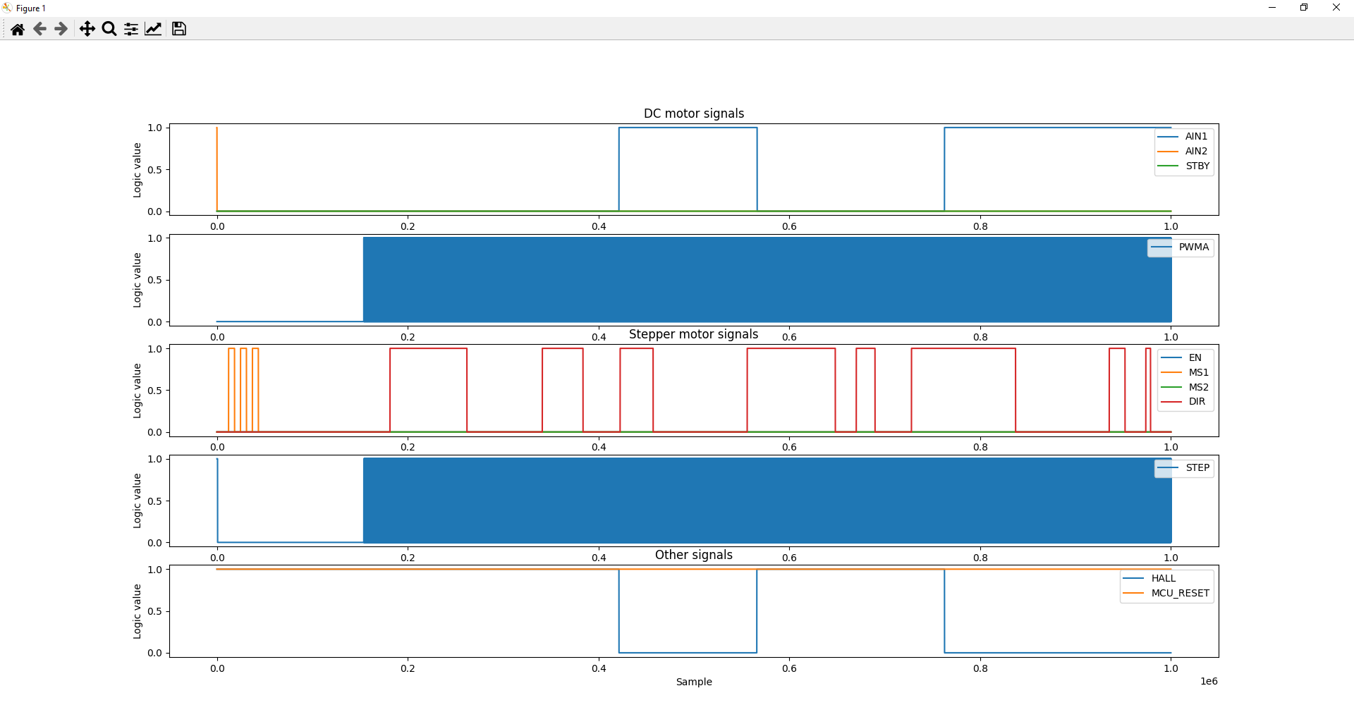
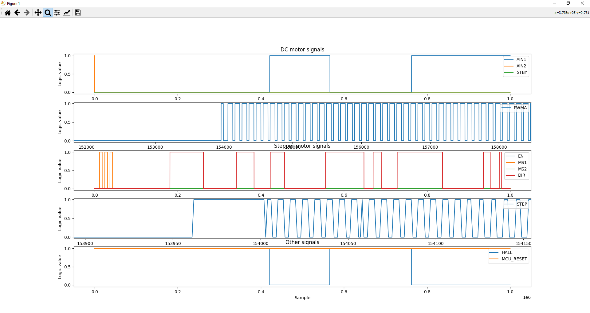
Data exported in a file can be visualized by running the plotting.m MATLAB script or the plotting.py Python program, or you can write your own program to plot the data.
Final Notes
For more guides and example projects for your Analog Discovery 2, please visit its Resource Center.
For more information about how to use WaveForms SDK, please visit the WaveForms SDK Reference Manual.
For technical support, please visit the Digilent Forums.


