Adding DDR Memory to a Microblaze Design
Add the MIG IP
When creating a design with DDR, it's best to add the DDR interface first, as it is typically also used to generate the clock or clocks that will be used by the rest of your design.
|
In the Board tab, right click on the DDR interface and select “Auto Connect”. This process will add a MIG (Memory Interface Generator) and the external DDR interface to the design. Two clock pins are also created, which will need to be modified. |
|

MIG Clocking
|
Delete the “clk_ref_i” pin. This can be accomplished either by right-clicking on the pin and selecting delete or by selecting and pressing the delete key. |
|

|
Verify that the “ui_addn_clk_0” pin has a frequency near 200 MHz by selecting it and looking at the “Frequency” value in the “Block Pin Properties” pane. |
|

|
Manually connect the “ui_addn_clk_0” pin to the “clk_ref_i” pin by clicking and dragging from one to the other. |
|

It's important to note that the “sys_clk_i” pin will not be constrained by the board files, and you will need to add a constraint file to map it to the corresponding pin location on the FPGA.
If your project doesn't contain the master Xilinx Design Constraint (XDC) file for your board, the dropdown below details how to add it. This file contains the constraints that your board places on designs using it - specific interfaces wired up to specific pins, clock frequencies, and FPGA bank voltages, for some examples. Click the dropdown below for a walkthrough of how to add this file to your project.
- Add a Master XDC File to a Vivado Project
-
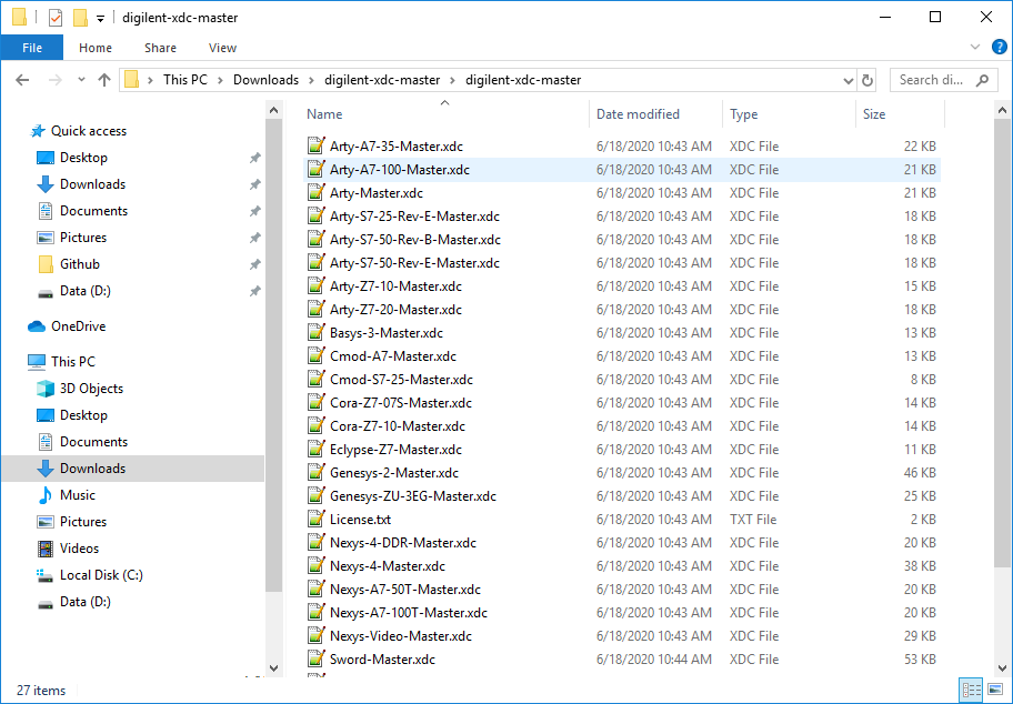
Download and extract digilent-xdc-master.zip. This file includes all of the latest template XDC files released for Digilent's boards, which are available on Github in the digilent-xdc repository.
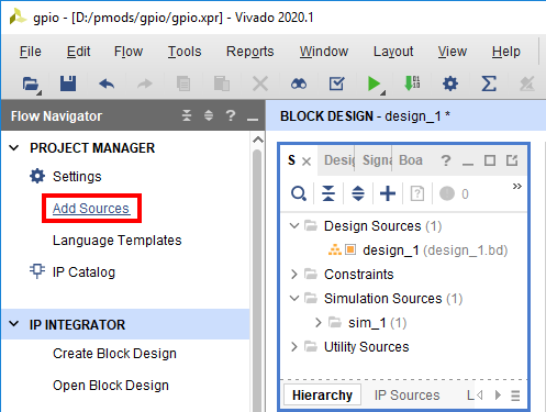
Returning to Vivado, click the Add Sources button in the Project Manager section of the Flow Navigator pane. This will launch a dialog that you can use to add a variety of types of source files to the project (or create new ones).
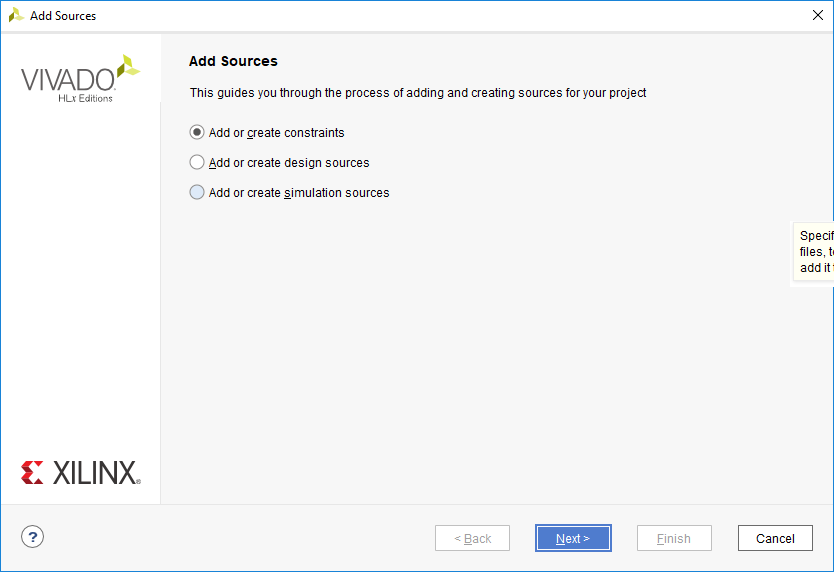
On the first screen, select Add or create constraints. Click Next to continue.
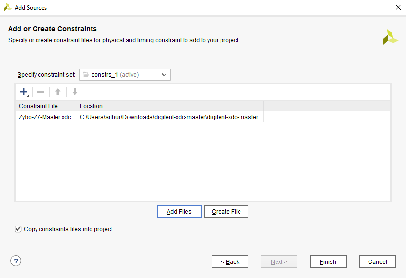
In the next screen, make sure that the constraint set specified (the one that the master XDC will be added to) is set to constrs_1, and that it is the active set. Click the Add Files button.

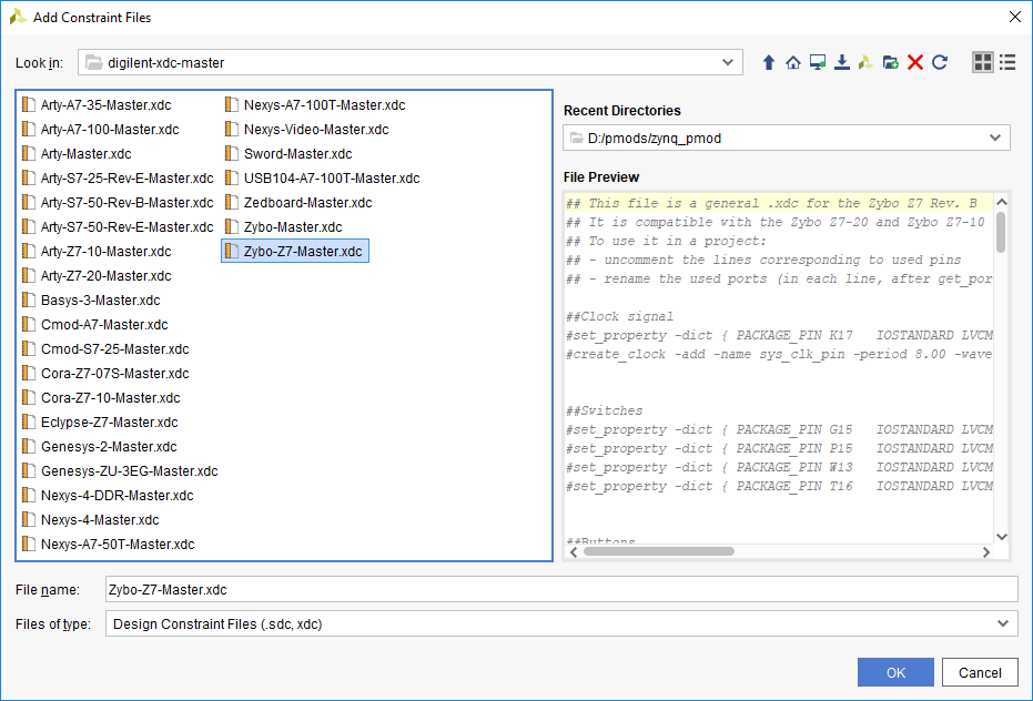
In the dialog that pops up, navigate to the folder that the digilent-xdc-master.zip file was extracted into. Highlight the XDC file for your board, then click OK to continue.
Back in the Add Sources dialog, make sure that your chosen constraint file appears in the table. Also, make sure that the Copy constraint files into project box is checked. If this box is unchecked, the file will be linked by your project, and any modifications made within the project will affect the version you downloaded. Since you may need to use this file again in other projects, copying the constraint file is recommended, so that you can always work from a fresh copy.
Click Finish to add the constraint file to your project.
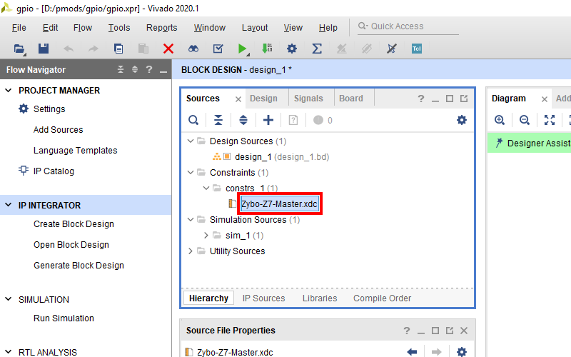
Once added, the XDC file will appear in the Sources tab (in the same pane as the Board tab). Double click it to open the file.


|
Find the set_property and create_clock constraints for your board's 100 MHz input clock, uncomment them by removing the
If your board has multiple clocks, the 100 MHz one can be determined by observing that the create_clock constraint specifies a Make sure to save your changes. |
|

MIG Reset
|
Next, the MIG's reset pin will be connected to the board's reset button. Click “Run Connection Automation” in the green bar at the top of the window. |
|

|
In the list to the left side of the dialog that pops up, make sure that the “sys_rst” box is checked. Click OK to connect the reset to the corresponding board part interface. |
|

Other MIG Ports
The MIG block may have other ports which will need to be connected to ensure that it works correctly. This section discusses each of those ports.
- Open this dropdown if your MIG has a "device_temp_i" port
-
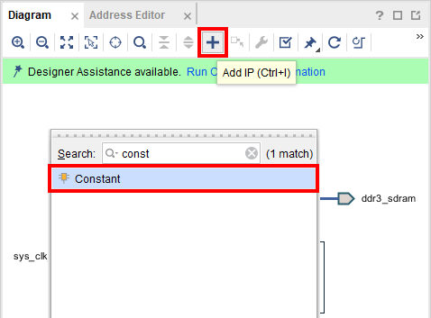
If your MIG block has a “device_temp_i” port, it means that the MIG is not using the chip's XADC analog-to-digital converter feature. We'll ground this port to prevent any warnings that it may throw. Add a “Constant” IP to the design.
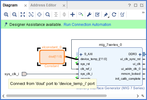
Double click on the block to open it's configuration wizard and modify it to have a Value of “0” and a Width of “12”.

Connect its output port to the “device_temp_i” port on the MIG.


Additional Clocks
If your design requires more clocks than just the ui_clk provided by the MIG, you will need to add a clocking wizard IP that is driven by the MIG's ui_clk.
|
Use the Add IP button to search for and add a Clocking Wizard to the design. |
|

|
Manually connect the Clocking Wizard's clk_in1 and reset ports to the MIG's ui_clk and ui_clk_sync_rst ports, respectively. |
|

|
Finally, double-click on the Clocking Wizard to open and configure it. The third tab, Output Clocks contains all of the settings required to specify how many clocks you need, and of what frequencies. The screenshot to the right shows the wizard configured to create a 100 MHz clk_out1 and a 50 MHz clk_out2. If your design requires additional clocks (such as for an ext_spi_clock pin), they should be added here. |
|

Note: If you aren't sure that you have all of the clocks you need, don't worry, you can always come back and add them by reconfiguring this IP. This task can be performed whenever in the design process it becomes necessary.
MIG Success
|
At the end of this process, the block design will look something like this: |
|
Connect the MIG to the Microblaze Processor
|
To connect the MIG's AXI interface to the processor, click the Run Connection Automation button in the green banner at the top of the block design. |
|

|
In the dialog that pops up, you will be presented with several options for interfaces that can be connected to other interfaces. Both the Microblaze's IC and DC ports, as well as the MIG's AXI port will appear. You should only run connection automation for one side of the connection - the S_AXI port, as shown in the screenshot to the right. Make sure that its box is checked. Check that the Master interface is set to “/microblaze_0 (Cached)”, indicating that the microblaze local memory will act as a cache for the DDR memory, then click OK to make the connections. |
|
