Getting Started with the Transistor Tester Adapter
Overview
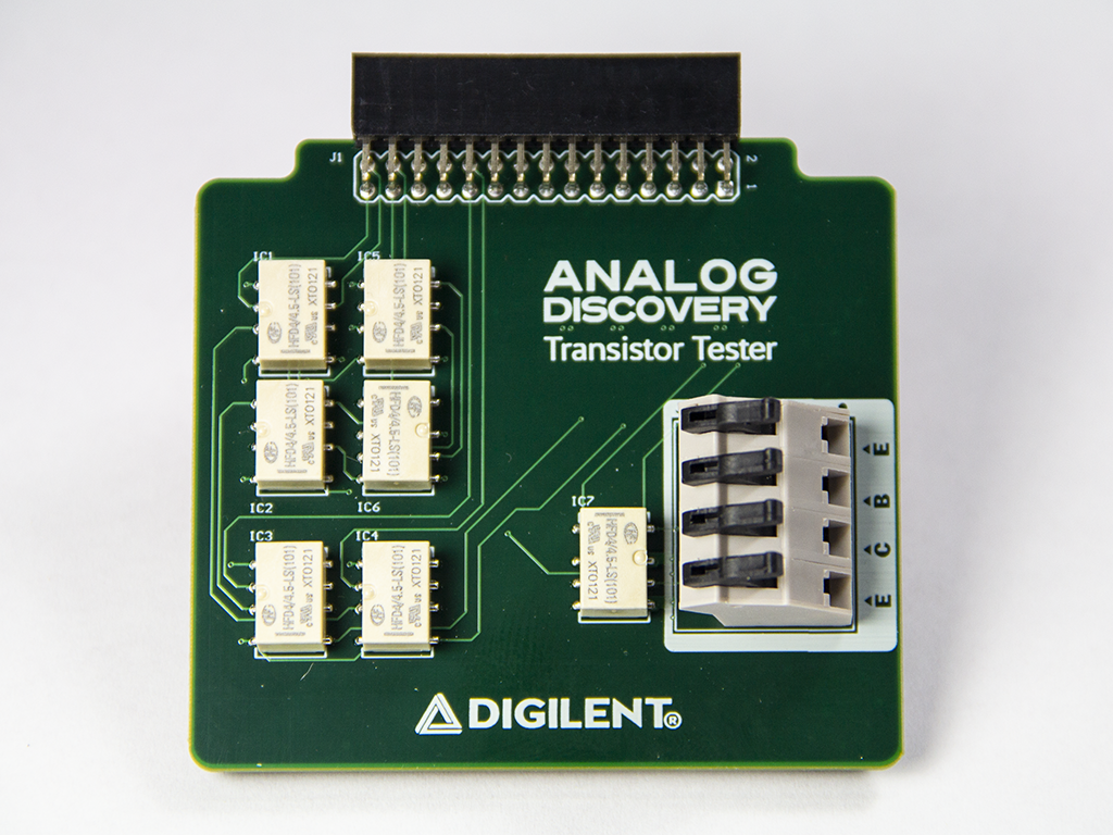
The Transistor Tester Adapter is a module that allows you to add the functionality of curve tracer to your test equipment suite. The Transistor Tester Adapter allows you to analyze the characteristics of discrete semiconductor devices like diodes, NPN and PNP transistors, and both P- and N-type FETs.
Inventory
- Your new Transistor Tester Adapter
- A computer, with the WaveForms application (version 3.16.3 or later) installed.
- Installation instructions can be found in the WaveForms Getting Started Guide.
1. Opening the Curve Tracer
1.1
Plug in the Transistor Tester Adapter and start WaveForms. Please make sure the device is connected. If no device is connected to the host computer when WaveForms launches, you will be presented with the Device Manager. Once you have the device plugged in and turned on, it will appear the Device Manager's list.
- Click on the device in the list to select it
- Click on the Select button to close the Device Manager
Note: “DEMO” devices are also listed in the Device Manager. “DEMO” devices allow you to use WaveForms and create projects without a physical device.
Note: The Device Manager can be opened by clicking on the “Connected Device” button in the bottom right corner of the screen or by selecting “Device Manager” from the “Settings” menu at the top of the screen.

1.2
Once the Welcome page loads, in the instrument panel at the left side of the window, click on the “Tracer” button to open the Curve Tracer instrument.

1.3
There are many options for taking a measurement with the Curve Tracer and Transistor Adapter. Please read through the Using the Curve Tracer guide for more information about the software interface. The remainder of this guide discusses how to set up the adapter.

2. Using the Transistor Tester Adapter
A Transistor Tester is also known as a curve tracer and the Transistor Tester Adapter is used to add curve tracer capability to your set of tools. A Curve Tracer plots the current (I) versus voltage (V) to create an I-V curve for an electronic device. The Transistor Tester allows you to create I-V curves for a variety of different kinds of transistors and diodes. The Transistor Tester will vary the voltage at the base of the device and measure the current response to create a graph like the one below.

In order to perform the analysis on the device under test (DUT) you will need to build a circuit like the one shown below. In this example, we are using a Fairchild SS8050 Epitaxial Silicon Transistor. The Transistor Tester Adapter has a 10 kΩ resistor on board for Rb and a 100 Ω resistor on board for Rc. Connect the C, B, and E points to the Transistor Tester Adapter Connector J2.

![]()
Next Steps
For more guides on how to use the Digilent Test & Measurement Device, return to the device's Resource Center, linked from Test and Measurement page of this wiki.
For more information on the Transistor Tester Adapter, check out its Resource Center.
For more information on WaveForms, visit the WaveForms Reference Manual.
For technical support, please visit the Test and Measurement section of the Digilent Forums.