Getting Started with WaveForms SDK
WaveForms SDK is a set of tools provided within the WaveForms installation that are used to develop custom software solutions that use Digilent Test and Measurement devices. The WaveForms SDK API is available in several programming languages, making it easy to use across many different platforms.
Normally, Test and Measurement devices are controlled and configured through the WaveForms application with a personal computer. Such a setup may be impossible in a given context, or an amount of automated signal measurement may be required beyond what WaveForms' scripting environment allows. WaveForms SDK gives the necessary tools to help craft the perfect solution for any problem.
This guide demonstrates the usage of some basic instruments and presents some patterns to help develop your own application. It is written with Python in mind, but users of other languages will still find it useful to illustrate the principles of working with the SDK.
For an up-to-date version of the scripts, check the GitHub repository, Python.
The GitHub material used by this guide has not been been updated since 2022. Newer hardware, such as the Analog Discovery 3, and additional software features that have been added since that time are not directly supported in Python modules and test examples provided by the GitHub material.
Alternate, fully supported examples for each supported programming language, maintained by the WaveForms development team, are provided with the WaveForms SDK download and may be found at the following locations:
- Windows 32-bit: C:\Program Files\Digilent\WaveFormsSDK\samples
- Windows 64-bit: C:\Program Files (x86)\Digilent\WaveFormsSDK\samples
- Linux: /usr/share/digilent/waveforms/samples
- macOS: /Applications/WaveForms.app/Contents/Resources/SDK/samples
The Python examples included with the WaveForms SDK download do not use any wrapper modules. However, an overview of how some of the underlying ctypes functions might be used to create modules is provided in the four numbered Workflow sections further down in this document.
Inventory
- A Digilent Test & Measurement Device
- A Computer with WaveForms Installed
- Both the WaveForms application and WaveForms SDK can be installed by following the WaveForms Getting Started Guide.
SDK Overview
WaveForms SDK is included with WaveForms and is installed alongside the application. The SDK is available to use with C/C++, C#, Python, and Visual Basic through a dynamic library (a module that contains data that can be used by other applications).
Another important file is the one that contains the definition of all constants. If you want to use the SDK from Python, this file is a Python module, while for C/C++ applications, the constants are defined in a header file.
Workflow
1. Importing the Constants and Loading the Dynamic Library
The WaveForms SDK Python functions use C-compatible data types, so along with the dynamic library and the module containing the constants, you will also need the ctypes module, which is installed together with Python by default.
As the first step of your project import the dwfconstants.py file to your project directory (it is located among the sample codes, in the py folder), then load the necessary modules and the dynamic library.
import ctypes                     # import the C compatible data types
from sys import platform, path    # this is needed to check the OS type and get the PATH
from os import sep                # OS specific file path separators

# load the dynamic library, get constants path (the path is OS specific)
if platform.startswith("win"):
    # on Windows
    dwf = ctypes.cdll.dwf
    constants_path = "C:" + sep + "Program Files (x86)" + sep + "Digilent" + sep + "WaveFormsSDK" + sep + "samples" + sep + "py"
elif platform.startswith("darwin"):
    # on macOS
    lib_path = sep + "Library" + sep + "Frameworks" + sep + "dwf.framework" + sep + "dwf"
    dwf = ctypes.cdll.LoadLibrary(lib_path)
    constants_path = sep + "Applications" + sep + "WaveForms.app" + sep + "Contents" + sep + "Resources" + sep + "SDK" + sep + "samples" + sep + "py"
else:
    # on Linux
    dwf = ctypes.cdll.LoadLibrary("libdwf.so")
    constants_path = sep + "usr" + sep + "share" + sep + "digilent" + sep + "waveforms" + sep + "samples" + sep + "py"

# import constants
path.append(constants_path)
import dwfconstants as constants
2. Connecting the Test & Measurement Device
The next step is to “open” your device. If you have only one Test & Measurement device connected, the simplest method is to ask the WaveForms SDK to connect to the first available device.
Opening a specific device and retrieving the name of the connected device is also possible (for more information, check the WaveForms SDK examples, or the GitHub repository).
class data:
    """
        stores the device handle and the device name
    """
    handle = ctypes.c_int(0)
    name = ""

def open():
    """
        open the first available device
    """
    # this is the device handle - it will be used by all functions to "address" the connected device
    device_handle = ctypes.c_int()
    # connect to the first available device
    dwf.FDwfDeviceOpen(ctypes.c_int(-1), ctypes.byref(device_handle))
    data.handle = device_handle
    return data
3. Using Instruments
The code snippets in this section present basic functionality of some instruments for some devices. For more possibilities (advanced features and more instruments) check the documentation of the WaveForms SDK, the available sample scripts and the GitHub repository.
- 3.1 Oscilloscope
-
3.1.1 Initialize the Scope
Before measuring with the oscilloscope, it must be set up. Change the values to fit your needs.
class data:
    """ stores the sampling frequency and the buffer size """
    sampling_frequency = 20e06
    buffer_size = 8192

def open(device_data, sampling_frequency=20e06, buffer_size=8192, offset=0, amplitude_range=5):
    """
        initialize the oscilloscope
        parameters: - device data
                    - sampling frequency in Hz, default is 20MHz
                    - buffer size, default is 8192
                    - offset voltage in Volts, default is 0V
                    - amplitude range in Volts, default is ±5V
    """
    # enable all channels
    dwf.FDwfAnalogInChannelEnableSet(device_data.handle, ctypes.c_int(0), ctypes.c_bool(True))

    # set offset voltage (in Volts)
    dwf.FDwfAnalogInChannelOffsetSet(device_data.handle, ctypes.c_int(0), ctypes.c_double(offset))

    # set range (maximum signal amplitude in Volts)
    dwf.FDwfAnalogInChannelRangeSet(device_data.handle, ctypes.c_int(0), ctypes.c_double(amplitude_range))

    # set the buffer size (data point in a recording)
    dwf.FDwfAnalogInBufferSizeSet(device_data.handle, ctypes.c_int(buffer_size))

    # set the acquisition frequency (in Hz)
    dwf.FDwfAnalogInFrequencySet(device_data.handle, ctypes.c_double(sampling_frequency))

    # disable averaging (for more info check the documentation)
    dwf.FDwfAnalogInChannelFilterSet(device_data.handle, ctypes.c_int(-1), constants.filterDecimate)
    data.sampling_frequency = sampling_frequency
    data.buffer_size = buffer_size
    return
3.1.2 Measure a Voltage
You can measure voltages, like with the Voltmeter instrument in WaveForms.
def measure(device_data, channel):
    """
        measure a voltage
        parameters: - device data
                    - the selected oscilloscope channel (1-2, or 1-4)

        returns:    - the measured voltage in Volts
    """
    # set up the instrument
    dwf.FDwfAnalogInConfigure(device_data.handle, ctypes.c_bool(False), ctypes.c_bool(False))

    # read data to an internal buffer
    dwf.FDwfAnalogInStatus(device_data.handle, ctypes.c_bool(False), ctypes.c_int(0))

    # extract data from that buffer
    voltage = ctypes.c_double()   # variable to store the measured voltage
    dwf.FDwfAnalogInStatusSample(device_data.handle, ctypes.c_int(channel - 1), ctypes.byref(voltage))

    # store the result as float
    voltage = voltage.value
    return voltage
3.1.3 Record a Signal
The most important feature of the oscilloscope is, that it can record signals. The recorded voltages can be stored in a list.
def record(device_data, channel):
    """
        record an analog signal
        parameters: - device data
                    - the selected oscilloscope channel (1-2, or 1-4)
        returns:    - buffer - a list with the recorded voltages
                    - time - a list with the time moments for each voltage in seconds (with the same index as "buffer")
    """
    # set up the instrument
    dwf.FDwfAnalogInConfigure(device_data.handle, ctypes.c_bool(False), ctypes.c_bool(True))

    # read data to an internal buffer
    while True:
        status = ctypes.c_byte()    # variable to store buffer status
        dwf.FDwfAnalogInStatus(device_data.handle, ctypes.c_bool(True), ctypes.byref(status))

        # check internal buffer status
        if status.value == constants.DwfStateDone.value:
                # exit loop when ready
                break

    # copy buffer
    buffer = (ctypes.c_double * data.buffer_size)()   # create an empty buffer
    dwf.FDwfAnalogInStatusData(device_data.handle, ctypes.c_int(channel - 1), buffer, ctypes.c_int(data.buffer_size))

    # calculate aquisition time
    time = range(0, data.buffer_size)
    time = [moment / data.sampling_frequency for moment in time]

    # convert into list
    buffer = [float(element) for element in buffer]
    return buffer, time
3.1.4 Reset the Scope
After usage, reset the oscilloscope to the default settings.
def close(device_data):
    """
        reset the scope
    """
    dwf.FDwfAnalogInReset(device_data.handle)
    return
- 3.2 Waveform Generator
-
3.2.1 Generate a Signal
Use the waveform generator to generate different signals.
You can define custom function names, to make the usage of the function easier.
class function:
    """ function names """
    custom = constants.funcCustom
    sine = constants.funcSine
    square = constants.funcSquare
    triangle = constants.funcTriangle
    noise = constants.funcNoise
    dc = constants.funcDC
    pulse = constants.funcPulse
    trapezium = constants.funcTrapezium
    sine_power = constants.funcSinePower
    ramp_up = constants.funcRampUp
    ramp_down = constants.funcRampDown
def generate(device_data, channel, function, offset, frequency=1e03, amplitude=1, symmetry=50, wait=0, run_time=0, repeat=0, data=[]):
    """
        generate an analog signal
        parameters: - device data
                    - the selected wavegen channel (1-2)
                    - function - possible: custom, sine, square, triangle, noise, ds, pulse, trapezium, sine_power, ramp_up, ramp_down
                    - offset voltage in Volts
                    - frequency in Hz, default is 1KHz
                    - amplitude in Volts, default is 1V
                    - signal symmetry in percentage, default is 50%
                    - wait time in seconds, default is 0s
                    - run time in seconds, default is infinite (0)
                    - repeat count, default is infinite (0)
                    - data - list of voltages, used only if function=custom, default is empty
    """
    # enable channel
    channel = ctypes.c_int(channel - 1)
    dwf.FDwfAnalogOutNodeEnableSet(device_data.handle, channel, constants.AnalogOutNodeCarrier, ctypes.c_bool(True))

    # set function type
    dwf.FDwfAnalogOutNodeFunctionSet(device_data.handle, channel, constants.AnalogOutNodeCarrier, function)

    # load data if the function type is custom
    if function == constants.funcCustom:
        data_length = len(data)
        buffer = (ctypes.c_double * data_length)()
        for index in range(0, len(buffer)):
            buffer[index] = ctypes.c_double(data[index])
        dwf.FDwfAnalogOutNodeDataSet(device_data.handle, channel, constants.AnalogOutNodeCarrier, buffer, ctypes.c_int(data_length))

    # set frequency
    dwf.FDwfAnalogOutNodeFrequencySet(device_data.handle, channel, constants.AnalogOutNodeCarrier, ctypes.c_double(frequency))

    # set amplitude or DC voltage
    dwf.FDwfAnalogOutNodeAmplitudeSet(device_data.handle, channel, constants.AnalogOutNodeCarrier, ctypes.c_double(amplitude))

    # set offset
    dwf.FDwfAnalogOutNodeOffsetSet(device_data.handle, channel, constants.AnalogOutNodeCarrier, ctypes.c_double(offset))

    # set symmetry
    dwf.FDwfAnalogOutNodeSymmetrySet(device_data.handle, channel, constants.AnalogOutNodeCarrier, ctypes.c_double(symmetry))

    # set running time limit
    dwf.FDwfAnalogOutRunSet(device_data.handle, channel, ctypes.c_double(run_time))

    # set wait time before start
    dwf.FDwfAnalogOutWaitSet(device_data.handle, channel, ctypes.c_double(wait))

    # set number of repeating cycles
    dwf.FDwfAnalogOutRepeatSet(device_data.handle, channel, ctypes.c_int(repeat))

    # start
    dwf.FDwfAnalogOutConfigure(device_data.handle, channel, ctypes.c_bool(True))
    return
3.2.2 Reset the Wavegen
After usage, reset the wavegen to the default settings.
def close(device_data, channel=0):
    """
        reset a wavegen channel, or all channels (channel=0)
    """
    channel = ctypes.c_int(channel - 1)
    dwf.FDwfAnalogOutReset(device_data.handle, channel)
    return
- 3.3 Power Supplies
-
- 3.3.1 Analog Discovery 3 Supplies
-
The Analog Discovery 3 has variable positive and negative supplies to set voltage levels.
def _switch_variable_(device_data, master_state, positive_state, negative_state, positive_voltage, negative_voltage):
    """
        turn the power supplies on/off
        parameters: - device data
                    - master switch - True = on, False = off
                    - positive supply switch - True = on, False = off
                    - negative supply switch - True = on, False = off
                    - positive supply voltage in Volts
                    - negative supply voltage in Volts
    """
    # set positive voltage
    positive_voltage = max(0, min(5, positive_voltage))
    dwf.FDwfAnalogIOChannelNodeSet(device_data.handle, ctypes.c_int(0), ctypes.c_int(1), ctypes.c_double(positive_voltage))

    # set negative voltage
    negative_voltage = max(-5, min(0, negative_voltage))
    dwf.FDwfAnalogIOChannelNodeSet(device_data.handle, ctypes.c_int(1), ctypes.c_int(1), ctypes.c_double(negative_voltage))

    # enable/disable the positive supply
    dwf.FDwfAnalogIOChannelNodeSet(device_data.handle, ctypes.c_int(0), ctypes.c_int(0), ctypes.c_int(positive_state))

    # enable the negative supply
    dwf.FDwfAnalogIOChannelNodeSet(device_data.handle, ctypes.c_int(1), ctypes.c_int(0), ctypes.c_int(negative_state))

    # start/stop the supplies - master switch
    dwf.FDwfAnalogIOEnableSet(device_data.handle, ctypes.c_int(master_state))
    return
- 3.3.2 Analog Discovery 2 and Analog Discovery Studio Supplies
-
These devices have variable positive and negative supplies, so a voltage level can also be set.
def _switch_variable_(device_data, master_state, positive_state, negative_state, positive_voltage, negative_voltage):
    """
        turn the power supplies on/off
        parameters: - device data
                    - master switch - True = on, False = off
                    - positive supply switch - True = on, False = off
                    - negative supply switch - True = on, False = off
                    - positive supply voltage in Volts
                    - negative supply voltage in Volts
    """
    # set positive voltage
    positive_voltage = max(0, min(5, positive_voltage))
    dwf.FDwfAnalogIOChannelNodeSet(device_data.handle, ctypes.c_int(0), ctypes.c_int(1), ctypes.c_double(positive_voltage))

    # set negative voltage
    negative_voltage = max(-5, min(0, negative_voltage))
    dwf.FDwfAnalogIOChannelNodeSet(device_data.handle, ctypes.c_int(1), ctypes.c_int(1), ctypes.c_double(negative_voltage))

    # enable/disable the positive supply
    dwf.FDwfAnalogIOChannelNodeSet(device_data.handle, ctypes.c_int(0), ctypes.c_int(0), ctypes.c_int(positive_state))

    # enable the negative supply
    dwf.FDwfAnalogIOChannelNodeSet(device_data.handle, ctypes.c_int(1), ctypes.c_int(0), ctypes.c_int(negative_state))

    # start/stop the supplies - master switch
    dwf.FDwfAnalogIOEnableSet(device_data.handle, ctypes.c_int(master_state))
    return
- 3.3.3 Analog Discovery (Legacy) Supplies
-
The Analog Discovery has only fixed supplies, so just a limited number of functions are available.
def _switch_fixed_(device_data, master_state, positive_state, negative_state):
    """
        turn the power supplies on/off
        parameters: - device data
                    - master switch - True = on, False = off
                    - positive supply switch - True = on, False = off
                    - negative supply switch - True = on, False = off
    """
    # enable/disable the positive supply
    dwf.FDwfAnalogIOChannelNodeSet(device_data.handle, ctypes.c_int(0), ctypes.c_int(0), ctypes.c_int(positive_state))

    # enable the negative supply
    dwf.FDwfAnalogIOChannelNodeSet(device_data.handle, ctypes.c_int(1), ctypes.c_int(0), ctypes.c_int(negative_state))

    # start/stop the supplies - master switch
    dwf.FDwfAnalogIOEnableSet(device_data.handle, ctypes.c_int(master_state))
    return
- 3.3.4 Analog Discovery Pro 3X50 and Digital Discovery Supplies
-
Devices with digital supplies have only positive voltage supplies with a variable voltage level between 1.2 and 3.3 Volts.
def _switch_digital_(device_data, master_state, voltage):
    """
        turn the power supplies on/off
        parameters: - device data
                    - master switch - True = on, False = off
                    - supply voltage in Volts
    """
    # set supply voltage
    voltage = max(1.2, min(3.3, voltage))
    dwf.FDwfAnalogIOChannelNodeSet(device_data.handle, ctypes.c_int(0), ctypes.c_int(0), ctypes.c_double(voltage))

    # start/stop the supplies - master switch
    dwf.FDwfAnalogIOEnableSet(device_data.handle, ctypes.c_int(master_state))
    return
- 3.3.5 Analog Discovery Pro 5250 6V Power Supply
-
You can set not only the voltage for the 6V power supply on the Analog Discovery 5250, but also the current limit, up to 1A.
def _switch_6V_(device_data, master_state, voltage, current=1):
    """
        turn the 6V supply on the ADP5250 on/off
        parameters: - master switch - True = on, False = off
                    - voltage in volts between 0-6
                    - current in amperes between 0-1
    """
    # set the voltage
    voltage = max(0, min(6, voltage))
    dwf.FDwfAnalogIOChannelNodeSet(device_data.handle, ctypes.c_int(0), ctypes.c_int(1), ctypes.c_double(voltage))

    # set the current
    current = max(0, min(1, current))
    dwf.FDwfAnalogIOChannelNodeSet(device_data.handle, ctypes.c_int(0), ctypes.c_int(2), ctypes.c_double(current))

    # start/stop the supply - master switch
    dwf.FDwfAnalogIOChannelNodeSet(device_data.handle, ctypes.c_int(0), ctypes.c_int(0), ctypes.c_double(float(master_state)))
    dwf.FDwfAnalogIOEnableSet(device_data.handle, ctypes.c_int(master_state))
    return
- 3.3.6 Analog Discovery Pro 5250 25V Power Supplies
-
The positive and negative isolated 25V power supplies are similar to the 6V one, but with a maximum current limit of 500mA.
def _switch_25V_(device_data, positive_state, negative_state, positive_voltage, negative_voltage, positive_current=0.5, negative_current=-0.5):
    """
        turn the 25V power supplies on/off on the ADP5250
        parameters: - positive supply switch - True = on, False = off
                    - negative supply switch - True = on, False = off
                    - positive supply voltage in Volts
                    - negative supply voltage in Volts
                    - positive supply current limit
                    - negative supply current limit
    """
    # set positive voltage
    positive_voltage = max(0, min(25, positive_voltage))
    dwf.FDwfAnalogIOChannelNodeSet(device_data.handle, ctypes.c_int(1), ctypes.c_int(1), ctypes.c_double(positive_voltage))

    # set negative voltage
    negative_voltage *= -1
    dwf.FDwfAnalogIOChannelNodeSet(device_data.handle, ctypes.c_int(2), ctypes.c_int(1), ctypes.c_double(negative_voltage))

    # set positive current limit
    positive_current = max(0, min(0.5, positive_current))
    dwf.FDwfAnalogIOChannelNodeSet(device_data.handle, ctypes.c_int(1), ctypes.c_int(2), ctypes.c_double(positive_current))

    # set negative current limit
    negative_current *= -1
    dwf.FDwfAnalogIOChannelNodeSet(device_data.handle, ctypes.c_int(2), ctypes.c_int(2), ctypes.c_double(negative_current))

    # enable/disable the supplies
    dwf.FDwfAnalogIOChannelNodeSet(device_data.handle, ctypes.c_int(1), ctypes.c_int(0), ctypes.c_double(float(positive_state)))
    dwf.FDwfAnalogIOChannelNodeSet(device_data.handle, ctypes.c_int(2), ctypes.c_int(0), ctypes.c_double(float(negative_state)))

    # master switch
    dwf.FDwfAnalogIOEnableSet(device_data.handle, ctypes.c_int(positive_state or negative_state))
    return
3.3.7 Wrapper Function
To make the usage of the above functions easier, you can create a wrapper function, which is able to call the function you need (if the device name is set).
class data:
    """ power supply parameters """
    master_state = False    # master switch
    state = False           # digital/6V/positive supply state
    positive_state = False  # positive supply switch
    negative_state = False  # negative supply switch
    positive_voltage = 0    # positive supply voltage
    negative_voltage = 0    # negative supply voltage
    voltage = 0             # digital/positive supply voltage
    positive_current = 0    # positive supply current
    negative_current = 0    # negative supply current
    current = 0             # digital/6V supply current

def switch(device_data, supplies_data):
    """
        turn the power supplies on/off
        parameters: - device data
                    - class containing supplies data:
                        - master_state
                        - state and/or positive_state and negative_state
                        - voltage and/or positive_voltage and negative_voltage
                        - current and/or positive_current and negative_current
    """
    if device_data.name == "Analog Discovery":
        # switch fixed supplies on AD
        supply_state = supplies_data.state or supplies_data.positive_state
        _switch_fixed_(device_data, supplies_data.master_state, supply_state, supplies_data.negative_state)

    elif device_data.name == "Analog Discovery 2" or device_data.name == "Analog Discovery Studio":
        # switch variable supplies on AD2
        supply_state = supplies_data.state or supplies_data.positive_state
        supply_voltage = supplies_data.voltage + supplies_data.positive_voltage
        _switch_variable_(device_data, supplies_data.master_state, supply_state, supplies_data.negative_state, supply_voltage, supplies_data.negative_voltage)

    elif device_data.name == "Digital Discovery" or device_data.name == "Analog Discovery Pro 3X50":
        # switch the digital supply on DD, or ADP3x50
        supply_state = supplies_data.master_state and (supplies_data.state or supplies_data.positive_state)
        supply_voltage = supplies_data.voltage + supplies_data.positive_voltage
        _switch_digital_(device_data, supply_state, supply_voltage)

    elif device_data.name == "Analog Discovery Pro 5250":
        # switch the 6V supply on ADP5250
        supply_state = supplies_data.master_state and supplies_data.state
        _switch_6V_(device_data, supply_state, supplies_data.voltage, supplies_data.current)
        # switch the 25V supplies on ADP5250
        supply_positive_state = supplies_data.master_state and supplies_data.positive_state
        supply_negative_state = supplies_data.master_state and supplies_data.negative_state
        _switch_25V_(device_data, supply_positive_state, supply_negative_state, supplies_data.positive_voltage, supplies_data.negative_voltage, supplies_data.positive_current, supplies_data.negative_current)
    return
3.3.8 Reset the Supplies
After usage, reset the supplies to the default settings.
def close(device_data):
    """
        reset the supplies
    """
    dwf.FDwfAnalogIOReset(device_data.handle)
    return
- 3.4 Digital Multimeter - Only on ADP5250
-
3.4.1 Initialize the DMM
Before measuring with the digital multimeter, it must be enabled.
def open(device_data):
    """
        initialize the digital multimeter
    """
    # enable the DMM
    dwf.FDwfAnalogIOChannelNodeSet(device_data.handle, ctypes.c_int(3), ctypes.c_int(0), ctypes.c_double(1.0))
    return
3.4.2 Measure With the DMM
You can use the digital multimeter to measure AC, or DC voltages (in Volts), with an input impedance of 10MΩ, or 10GΩ, low (<100mA), or high AC, or DC currents (up to 10A), resistance, conductance, temperature and more, with automatic, or fixed range.
def measure(device_data, mode, ac=False, range=0, high_impedance=False):
    """
        measure a voltage/current/resistance/continuity/temperature
        parameters: - device data
                    - mode: "voltage", "low current", "high current", "resistance", "continuity", "diode", "temperature"
                    - ac: True means AC value, False means DC value, default is DC
                    - range: voltage/current/resistance/temperature range, 0 means auto, default is auto
                    - high_impedance: input impedance for DC voltage measurement, False means 10MΩ, True means 10GΩ, default is 10MΩ

        returns:    - the measured value in V/A/Ω/°C, or None on error
    """
    # set voltage mode
    if mode == "voltage":
        # set coupling
        if ac:
            dwf.FDwfAnalogIOChannelNodeSet(device_data.handle, ctypes.c_int(3), ctypes.c_int(1), constants.DwfDmmACVoltage)
        else:
            dwf.FDwfAnalogIOChannelNodeSet(device_data.handle, ctypes.c_int(3), ctypes.c_int(1), constants.DwfDmmDCVoltage)

        # set input impedance
        if high_impedance:
            dwf.FDwfAnalogIOChannelNodeSet(device_data.handle, ctypes.c_int(3), ctypes.c_int(5), ctypes.c_double(1))
        else:
            dwf.FDwfAnalogIOChannelNodeSet(device_data.handle, ctypes.c_int(3), ctypes.c_int(5), ctypes.c_double(0))

    # set high current mode
    elif mode == "high current":
        # set coupling
        if ac:
            dwf.FDwfAnalogIOChannelNodeSet(device_data.handle, ctypes.c_int(3), ctypes.c_int(1), constants.DwfDmmACCurrent)
        else:
            dwf.FDwfAnalogIOChannelNodeSet(device_data.handle, ctypes.c_int(3), ctypes.c_int(1), constants.DwfDmmDCCurrent)

    # set low current mode
    elif mode == "low current":
        # set coupling
        if ac:
            dwf.FDwfAnalogIOChannelNodeSet(device_data.handle, ctypes.c_int(3), ctypes.c_int(1), constants.DwfDmmACLowCurrent)
        else:
            dwf.FDwfAnalogIOChannelNodeSet(device_data.handle, ctypes.c_int(3), ctypes.c_int(1), constants.DwfDmmDCLowCurrent)

    # set resistance mode
    elif mode == "resistance":
        dwf.FDwfAnalogIOChannelNodeSet(device_data.handle, ctypes.c_int(3), ctypes.c_int(1), constants.DwfDmmResistance)

    # set continuity mode
    elif mode == "continuity":
        dwf.FDwfAnalogIOChannelNodeSet(device_data.handle, ctypes.c_int(3), ctypes.c_int(1), constants.DwfDmmContinuity)

    # set diode mode
    elif mode == "diode":
        dwf.FDwfAnalogIOChannelNodeSet(device_data.handle, ctypes.c_int(3), ctypes.c_int(1), constants.DwfDmmDiode)

    # set temperature mode
    elif mode == "temperature":
        dwf.FDwfAnalogIOChannelNodeSet(device_data.handle, ctypes.c_int(3), ctypes.c_int(1), constants.DwfDmmTemperature)

    # set range
    dwf.FDwfAnalogIOChannelNodeSet(device_data.handle, ctypes.c_int(3), ctypes.c_int(2), ctypes.c_double(range))

    # fetch analog I/O status
    if dwf.FDwfAnalogIOStatus(device_data.handle) == 0:
        # signal error
        return None

    # get reading
    measurement = ctypes.c_double()
    dwf.FDwfAnalogIOChannelNodeStatus(device_data.handle, ctypes.c_int(3), ctypes.c_int(3), ctypes.byref(measurement))

    return measurement.value
3.4.3 Reset the DMM
After usage, reset the instrument to the default settings.
def close(device_data):
    """
        reset the instrument
    """
    # disable the DMM
    dwf.FDwfAnalogIOChannelNodeSet(device_data.handle, ctypes.c_int(3), ctypes.c_int(0), ctypes.c_double(0))
    # reset the instrument
    dwf.FDwfAnalogIOReset(device_data.handle)
    return
- 3.5 Logic Analyzer
-
3.5.1 Initialize the Logic Analyzer
Before measuring with the logic analyzer, it must be set up. Change the values to fit your needs.
class data:
    """ stores the sampling frequency and the buffer size """
    sampling_frequency = 100e06
    buffer_size = 4096

def open(device_data, sampling_frequency=100e06, buffer_size=4096):
    """
        initialize the logic analyzer
        parameters: - device data
                    - sampling frequency in Hz, default is 100MHz
                    - buffer size, default is 4096
    """
    # get internal clock frequency
    internal_frequency = ctypes.c_double()
    dwf.FDwfDigitalInInternalClockInfo(device_data.handle, ctypes.byref(internal_frequency))

    # set clock frequency divider (needed for lower frequency input signals)
    dwf.FDwfDigitalInDividerSet(device_data.handle, ctypes.c_int(int(internal_frequency.value / sampling_frequency)))

    # set 16-bit sample format
    dwf.FDwfDigitalInSampleFormatSet(device_data.handle, ctypes.c_int(16))

    # set buffer size
    dwf.FDwfDigitalInBufferSizeSet(device_data.handle, ctypes.c_int(buffer_size))
    data.sampling_frequency = sampling_frequency
    data.buffer_size = buffer_size
    return
3.5.2 Record Logic Signals
Record logic signals in a list of lists, then select the one specific for the required DIO line.
def record(device_data, channel):
    """
        initialize the logic analyzer
        parameters: - device data
                    - channel - the selected DIO line number
        returns:    - buffer - a list with the recorded logic values
                    - time - a list with the time moments for each value in seconds (with the same index as "buffer")
    """
    # set up the instrument
    dwf.FDwfDigitalInConfigure(device_data.handle, ctypes.c_bool(False), ctypes.c_bool(True))

    # read data to an internal buffer
    while True:
        status = ctypes.c_byte()    # variable to store buffer status
        dwf.FDwfDigitalInStatus(device_data.handle, ctypes.c_bool(True), ctypes.byref(status))

        if status.value == constants.stsDone.value:
            # exit loop when finished
            break

    # get samples
    buffer = (ctypes.c_uint16 * data.buffer_size)()
    dwf.FDwfDigitalInStatusData(device_data.handle, buffer, ctypes.c_int(2 * data.buffer_size))

    # convert buffer to list of lists of integers
    buffer = [int(element) for element in buffer]
    result = [[] for _ in range(16)]
    for point in buffer:
        for index in range(16):
            result[index].append(point & (1 << index))

    # calculate acquisition time
    time = range(0, data.buffer_size)
    time = [moment / data.sampling_frequency for moment in time]

    # get channel specific data
    buffer = result[channel]
    return buffer, time
3.5.3 Reset the Logic Analyzer
After usage, reset the logic analyzer to the default settings.
def close(device_data):
    """
        reset the instrument
    """
    dwf.FDwfDigitalInReset(device_data.handle)
    return
- 3.6 Pattern Generator
-
3.6.1 Generate Logic Signals
Configure the pattern generator to generate logic signals.
You can use a DIO line for pattern generation only if the respective line is configured as input and set to LOW state by the static I/O instrument (these are the default settings for all lines).
You can define custom function, trigger source and idle state names, to make the usage of the function easier.
class function:
    """ function names """
    pulse = constants.DwfDigitalOutTypePulse
    custom = constants.DwfDigitalOutTypeCustom
    random = constants.DwfDigitalOutTypeRandom

class trigger_source:
    """ trigger source names """
    none = constants.trigsrcNone
    analog = constants.trigsrcDetectorAnalogIn
    digital = constants.trigsrcDetectorDigitalIn
    external = [None, constants.trigsrcExternal1, constants.trigsrcExternal2, constants.trigsrcExternal3, constants.trigsrcExternal4]

class idle_state:
    """ channel idle states """
    initial = constants.DwfDigitalOutIdleInit
    high = constants.DwfDigitalOutIdleHigh
    low = constants.DwfDigitalOutIdleLow
    high_impedance = constants.DwfDigitalOutIdleZet
def generate(device_data, channel, function, frequency, duty_cycle=50, data=[], wait=0, repeat=0, run_time=0, idle=idle_state.initial, trigger_enabled=False, trigger_source=trigger_source.none, trigger_edge_rising=True):
    """
        generate a logic signal

        parameters: - channel - the selected DIO line number
                    - function - possible: pulse, custom, random
                    - frequency in Hz
                    - duty cycle in percentage, used only if function = pulse, default is 50%
                    - data list, used only if function = custom, default is empty
                    - wait time in seconds, default is 0 seconds
                    - repeat count, default is infinite (0)
                    - run_time: in seconds, 0=infinite, "auto"=auto
                    - idle - possible: initial, high, low, high_impedance, default = initial
                    - trigger_enabled - include/exclude trigger from repeat cycle
                    - trigger_source - possible: none, analog, digital, external[1-4]
                    - trigger_edge_rising - True means rising, False means falling, None means either, default is rising
    """
    # get internal clock frequency
    internal_frequency = ctypes.c_double()
    dwf.FDwfDigitalOutInternalClockInfo(device_data.handle, ctypes.byref(internal_frequency))

    # get counter value range
    counter_limit = ctypes.c_uint()
    dwf.FDwfDigitalOutCounterInfo(device_data.handle, ctypes.c_int(channel), ctypes.c_int(0), ctypes.byref(counter_limit))

    # calculate the divider for the given signal frequency
    if function == constants.DwfDigitalOutTypePulse:
        divider = int(-(-(internal_frequency.value / frequency) // counter_limit.value))
    else:
        divider = int(internal_frequency.value / frequency)

    # enable the respective channel
    dwf.FDwfDigitalOutEnableSet(device_data.handle, ctypes.c_int(channel), ctypes.c_int(1))

    # set output type
    dwf.FDwfDigitalOutTypeSet(device_data.handle, ctypes.c_int(channel), function)

    # set frequency
    dwf.FDwfDigitalOutDividerSet(device_data.handle, ctypes.c_int(channel), ctypes.c_int(divider))

    # set idle state
    dwf.FDwfDigitalOutIdleSet(device_data.handle, ctypes.c_int(channel), idle)

    # set PWM signal duty cycle
    if function == constants.DwfDigitalOutTypePulse:
        # calculate counter steps to get the required frequency
        steps = int(round(internal_frequency.value / frequency / divider))
        # calculate steps for low and high parts of the period
        high_steps = int(steps * duty_cycle / 100)
        low_steps = int(steps - high_steps)
        dwf.FDwfDigitalOutCounterSet(device_data.handle, ctypes.c_int(channel), ctypes.c_int(low_steps), ctypes.c_int(high_steps))

    # load custom signal data
    elif function == constants.DwfDigitalOutTypeCustom:
        # format data
        buffer = (ctypes.c_ubyte * ((len(data) + 7) >> 3))(0)
        for index in range(len(data)):
            if data[index] != 0:
                buffer[index >> 3] |= 1 << (index & 7)

        # load data
        dwf.FDwfDigitalOutDataSet(device_data.handle, ctypes.c_int(channel), ctypes.byref(buffer), ctypes.c_int(len(data)))

    # calculate run length
    if run_time == "auto":
        run_time = len(data) / frequency

    # set wait time
    dwf.FDwfDigitalOutWaitSet(device_data.handle, ctypes.c_double(wait))

    # set repeat count
    dwf.FDwfDigitalOutRepeatSet(device_data.handle, ctypes.c_int(repeat))

    # set run length
    dwf.FDwfDigitalOutRunSet(device_data.handle, ctypes.c_double(run_time))

    # enable triggering
    dwf.FDwfDigitalOutRepeatTriggerSet(device_data.handle, ctypes.c_int(trigger_enabled))

    if trigger_enabled:
        # set trigger source
        dwf.FDwfDigitalOutTriggerSourceSet(device_data.handle, trigger_source)

        # set trigger slope
        if trigger_edge_rising == True:
            # rising edge
            dwf.FDwfDigitalOutTriggerSlopeSet(device_data.handle, constants.DwfTriggerSlopeRise)
        elif trigger_edge_rising == False:
            # falling edge
            dwf.FDwfDigitalOutTriggerSlopeSet(device_data.handle, constants.DwfTriggerSlopeFall)
        elif trigger_edge_rising == None:
            # either edge
            dwf.FDwfDigitalOutTriggerSlopeSet(device_data.handle, constants.DwfTriggerSlopeEither)

    # start generating the signal
    dwf.FDwfDigitalOutConfigure(device_data.handle, ctypes.c_int(True))
    return
3.6.2 Reset the Pattern Generator
After usage, reset the pattern generator to the default settings.
def close(device_data):
    """
        reset the instrument
    """
    dwf.FDwfDigitalOutReset(device_data.handle)
    return
- 3.7 Static I/O
-
3.7.1 Set Pins As Input Or As Output
Each digital pin of the Test & Measurement device can be used only as input, or as output at a time. The default settings for each line are input states.
def set_mode(device_data, channel, output):
    """
        set a DIO line as input, or as output
        parameters: - device data
                    - selected DIO channel number
                    - True means output, False means input
    """
    # load current state of the output enable buffer
    mask = ctypes.c_uint16()
    dwf.FDwfDigitalIOOutputEnableGet(device_data.handle, ctypes.byref(mask))

    # convert mask to list
    mask = list(bin(mask.value)[2:].zfill(16))

    # set bit in mask
    if output:
        mask[15 - channel] = "1"
    else:
        mask[15 - channel] = "0"

    # convert mask to number
    mask = "".join(element for element in mask)
    mask = int(mask, 2)

    # set the pin to output
    dwf.FDwfDigitalIOOutputEnableSet(device_data.handle, ctypes.c_int(mask))
    return
3.7.2 Get Pin State
Read the state of a DIO line with the following code snippet:
def get_state(device_data, channel):
    """
        get the state of a DIO line
        parameters: - device data
                    - selected DIO channel number
        returns:    - True if the channel is HIGH, or False, if the channel is LOW
    """
    # load internal buffer with current state of the pins
    dwf.FDwfDigitalIOStatus(device_data.handle)

    # get the current state of the pins
    data = ctypes.c_uint32()  # variable for this current state
    dwf.FDwfDigitalIOInputStatus(device_data.handle, ctypes.byref(data))

    # convert the state to a 16 character binary string
    data = list(bin(data.value)[2:].zfill(16))

    # check the required bit
    if data[15 - channel] != "0":
        value = True
    else:
        value = False
    return value
3.7.3 Set Pin State
To set the state of a DIO line, it must be set as output!
def set_state(device_data, channel, value):
    """
        set a DIO line as input, or as output
        parameters: - device data
                    - selected DIO channel number
                    - True means HIGH, False means LOW
    """
    # load current state of the output state buffer
    mask = ctypes.c_uint16()
    dwf.FDwfDigitalIOOutputGet(device_data.handle, ctypes.byref(mask))

    # convert mask to list
    mask = list(bin(mask.value)[2:].zfill(16))

    # set bit in mask
    if value:
        mask[15 - channel] = "1"
    else:
        mask[15 - channel] = "0"

    # convert mask to number
    mask = "".join(element for element in mask)
    mask = int(mask, 2)

    # set the pin state
    dwf.FDwfDigitalIOOutputSet(device_data.handle, ctypes.c_int(mask))
    return
3.7.4 Reset the Static I/O
After usage, reset the instrument to the default settings.
def close(device_data):
    """
        reset the instrument
    """
    dwf.FDwfDigitalIOReset(device_data.handle)
    return
- 3.8 Protocol: UART
-
3.8.1 Initialize the Interface
Before using a communication interface, it must be initialized by setting the communication parameters to the desired values.
def open(device_data, rx, tx, baud_rate=9600, parity=None, data_bits=8, stop_bits=1):
    """
        initializes UART communication

        parameters: - device data
                    - rx (DIO line used to receive data)
                    - tx (DIO line used to send data)
                    - baud_rate (communication speed, default is 9600 bits/s)
                    - parity possible: None (default), True means even, False means odd
                    - data_bits (default is 8)
                    - stop_bits (default is 1)
    """
    # set baud rate
    dwf.FDwfDigitalUartRateSet(device_data.handle, ctypes.c_double(baud_rate))

    # set communication channels
    dwf.FDwfDigitalUartTxSet(device_data.handle, ctypes.c_int(tx))
    dwf.FDwfDigitalUartRxSet(device_data.handle, ctypes.c_int(rx))

    # set data bit count
    dwf.FDwfDigitalUartBitsSet(device_data.handle, ctypes.c_int(data_bits))

    # set parity bit requirements
    if parity == True:
        parity = 2
    elif parity == False:
        parity = 1
    else:
        parity = 0
    dwf.FDwfDigitalUartParitySet(device_data.handle, ctypes.c_int(parity))

    # set stop bit count
    dwf.FDwfDigitalUartStopSet(device_data.handle, ctypes.c_double(stop_bits))

    # initialize channels with idle levels

    # dummy read
    dummy_buffer = ctypes.create_string_buffer(0)
    dummy_buffer = ctypes.c_int(0)
    dummy_parity_flag = ctypes.c_int(0)
    dwf.FDwfDigitalUartRx(device_data.handle, dummy_buffer, ctypes.c_int(0), ctypes.byref(dummy_buffer), ctypes.byref(dummy_parity_flag))

    # dummy write
    dwf.FDwfDigitalUartTx(device_data.handle, dummy_buffer, ctypes.c_int(0))
    return
3.8.2 Receive Data
Use the function to the right to read data on an initialized UART interface.
def read(device_data):
    """
        receives data from UART

        parameters: - device data
        return:     - integer list containing the received bytes
                    - error message or empty string
    """
    # variable to store results
    error = ""
    rx_data = []

    # create empty string buffer
    data = (ctypes.c_ubyte * 8193)()

    # character counter
    count = ctypes.c_int(0)

    # parity flag
    parity_flag= ctypes.c_int(0)

    # read up to 8k characters
    dwf.FDwfDigitalUartRx(device_data.handle, data, ctypes.c_int(ctypes.sizeof(data)-1), ctypes.byref(count), ctypes.byref(parity_flag))

    # append current data chunks
    for index in range(0, count.value):
        rx_data.append(int(data[index]))

    # ensure data integrity
    while count.value > 0:
        # create empty string buffer
        data = (ctypes.c_ubyte * 8193)()

        # character counter
        count = ctypes.c_int(0)

        # parity flag
        parity_flag= ctypes.c_int(0)

        # read up to 8k characters
        dwf.FDwfDigitalUartRx(device_data.handle, data, ctypes.c_int(ctypes.sizeof(data)-1), ctypes.byref(count), ctypes.byref(parity_flag))
        # append current data chunks
        for index in range(0, count.value):
            rx_data.append(int(data[index]))

        # check for not acknowledged
        if error == "":
            if parity_flag.value < 0:
                error = "Buffer overflow"
            elif parity_flag.value > 0:
                error = "Parity error: index {}".format(parity_flag.value)
    return rx_data,
3.8.3 Send Data
Use the function to the right to send data on an initialized UART interface to another device.
def write(device_data, data):
    """
        send data through UART

        parameters: - data of type string, int, or list of characters/integers
    """
    # cast data
    if type(data) == int:
        data = "".join(chr (data))
    elif type(data) == list:
        data = "".join(chr (element) for element in data)

    # encode the string into a string buffer
    data = ctypes.create_string_buffer(data.encode("UTF-8"))

    # send text, trim zero ending
    dwf.FDwfDigitalUartTx(device_data.handle, data, ctypes.c_int(ctypes.sizeof(data)-1))
    return
3.8.4 Reset the Interface
After usage, reset the instrument to the default settings.
def close(device_data):
    """
        reset the uart interface
    """
    dwf.FDwfDigitalUartReset(device_data.handle)
    return
- 3.9 Protocol: SPI
-
3.9.1 Initialize the Interface
Before using a communication interface, it must be initialized by setting the communication parameters to the desired values.
def open(device_data, cs, sck, miso=None, mosi=None, clk_frequency=1e06, mode=0, order=True):
    """
        initializes SPI communication
        parameters: - device data
                    - cs (DIO line used for chip select)
                    - sck (DIO line used for serial clock)
                    - miso (DIO line used for master in - slave out, optional)
                    - mosi (DIO line used for master out - slave in, optional)
                    - frequency (communication frequency in Hz, default is 1MHz)
                    - mode (SPI mode: 0: CPOL=0, CPHA=0; 1: CPOL-0, CPHA=1; 2: CPOL=1, CPHA=0; 3: CPOL=1, CPHA=1)
                    - order (endianness, True means MSB first - default, False means LSB first)
    """
    # set the clock frequency
    dwf.FDwfDigitalSpiFrequencySet(device_data.handle, ctypes.c_double(clk_frequency))

    # set the clock pin
    dwf.FDwfDigitalSpiClockSet(device_data.handle, ctypes.c_int(sck))

    if mosi != None:
        # set the mosi pin
        dwf.FDwfDigitalSpiDataSet(device_data.handle, ctypes.c_int(0), ctypes.c_int(mosi))

        # set the initial state
        dwf.FDwfDigitalSpiIdleSet(device_data.handle, ctypes.c_int(0), constants.DwfDigitalOutIdleZet)

    if miso != None:
        # set the miso pin
        dwf.FDwfDigitalSpiDataSet(device_data.handle, ctypes.c_int(1), ctypes.c_int(miso))

        # set the initial state
        dwf.FDwfDigitalSpiIdleSet(device_data.handle, ctypes.c_int(1), constants.DwfDigitalOutIdleZet)

    # set the SPI mode
    dwf.FDwfDigitalSpiModeSet(device_data.handle, ctypes.c_int(mode))

    # set endianness
    if order:
        # MSB first
        dwf.FDwfDigitalSpiOrderSet(device_data.handle, ctypes.c_int(1))
    else:
        # LSB first
        dwf.FDwfDigitalSpiOrderSet(device_data.handle, ctypes.c_int(0))

    # set the cs pin HIGH
    dwf.FDwfDigitalSpiSelect(device_data.handle, ctypes.c_int(cs), ctypes.c_int(1))

    # dummy write
    dwf.FDwfDigitalSpiWriteOne(device_data.handle, ctypes.c_int(1), ctypes.c_int(0), ctypes.c_int(0))
    return
3.9.2 Receive Data
Use the function to the right to read data on an initialized SPI interface.
def read(device_data, count, cs):
    """
        receives data from SPI
        parameters: - device data
                    - count (number of bytes to receive)
                    - chip select line number
        return:     - integer list containing the received bytes
    """
    # enable the chip select line
    dwf.FDwfDigitalSpiSelect(device_data.handle, ctypes.c_int(cs), ctypes.c_int(0))

    # create buffer to store data
    buffer = (ctypes.c_ubyte*count)()

    # read array of 8 bit elements
    dwf.FDwfDigitalSpiRead(device_data.handle, ctypes.c_int(1), ctypes.c_int(8), buffer, ctypes.c_int(len(buffer)))

    # disable the chip select line
    dwf.FDwfDigitalSpiSelect(device_data.handle, ctypes.c_int(cs), ctypes.c_int(1))

    # decode data
    data = [int(element) for element in buffer]
    return data
3.9.3 Send Data
Use the function to the right to send data on an initialized SPI interface to another device.
def write(device_data, data, cs):
    """
        send data through SPI
        parameters: - device data
                    - data of type string, int, or list of characters/integers
                    - chip select line number
    """
    # cast data
    if type(data) == int:
        data = "".join(chr (data))
    elif type(data) == list:
        data = "".join(chr (element) for element in data)

    # enable the chip select line
    dwf.FDwfDigitalSpiSelect(device_data.handle, ctypes.c_int(cs), ctypes.c_int(0))

    # create buffer to write
    data = bytes(data, "utf-8")
    buffer = (ctypes.c_ubyte * len(data))()
    for index in range(0, len(buffer)):
        buffer[index] = ctypes.c_ubyte(data[index])

    # write array of 8 bit elements
    dwf.FDwfDigitalSpiWrite(device_data.handle, ctypes.c_int(1), ctypes.c_int(8), buffer, ctypes.c_int(len(buffer)))

    # disable the chip select line
    dwf.FDwfDigitalSpiSelect(device_data.handle, ctypes.c_int(cs), ctypes.c_int(1))
    return
3.9.4 Reset the Interface
After usage, reset the instrument to the default settings.
def close(device_data):
    """
        reset the spi interface
    """
    dwf.FDwfDigitalSpiReset(device_data.handle)
    return
- 3.10 Protocol: I2C
-
3.10.1 Initialize the Interface
Before using a communication interface, it must be initialized by setting the communication parameters to the desired values.
def open(device_data, sda, scl, clk_rate=100e03, stretching=True):
    """
        initializes I2C communication
        parameters: - device data
                    - sda (DIO line used for data)
                    - scl (DIO line used for clock)
                    - rate (clock frequency in Hz, default is 100KHz)
                    - stretching (enables/disables clock stretching)
        returns:    - error message or empty string
    """
    # reset the interface
    dwf.FDwfDigitalI2cReset(device_data.handle)

    # clock stretching
    if stretching:
        dwf.FDwfDigitalI2cStretchSet(device_data.handle, ctypes.c_int(1))
    else:
        dwf.FDwfDigitalI2cStretchSet(device_data.handle, ctypes.c_int(0))

    # set clock frequency
    dwf.FDwfDigitalI2cRateSet(device_data.handle, ctypes.c_double(clk_rate))

    #  set communication lines
    dwf.FDwfDigitalI2cSclSet(device_data.handle, ctypes.c_int(scl))
    dwf.FDwfDigitalI2cSdaSet(device_data.handle, ctypes.c_int(sda))

    # check bus
    nak = ctypes.c_int()
    dwf.FDwfDigitalI2cClear(device_data.handle, ctypes.byref(nak))
    if nak.value == 0:
        return "Error: I2C bus lockup"

    # write 0 bytes
    dwf.FDwfDigitalI2cWrite(device_data.handle, ctypes.c_int(0), ctypes.c_int(0), ctypes.c_int(0), ctypes.byref(nak))
    if nak.value != 0:
        return "NAK: index " + str(nak.value)
    return ""
3.10.2 Receive Data
Use the function to the right to read data on an initialized I2C interface.
def read(device_data, count, address):
    """
        receives data from I2C

        parameters: - device data
                    - count (number of bytes to receive)
                    - address (8-bit address of the slave device)

        return:     - integer list containing the received bytes
                    - error message or empty string
    """
    # create buffer to store data
    buffer = (ctypes.c_ubyte * count)()

    # receive
    nak = ctypes.c_int()
    dwf.FDwfDigitalI2cRead(device_data.handle, ctypes.c_int(address << 1), buffer, ctypes.c_int(count), ctypes.byref(nak))

    # decode data
    data = [int(element) for element in buffer]

    # check for not acknowledged
    if nak.value != 0:
        return data, "NAK: index " + str(nak.value)
    return data, ""
3.10.3 Send Data
Use the function to the right to send data on an initialized I2C interface to another device.
def write(device_data, data, address):
    """
        send data through I2C

        parameters: - device data
                    - data of type string, int, or list of characters/integers
                    - address (8-bit address of the slave device)

        returns:    - error message or empty string
    """
    # cast data
    if type(data) == int:
        data = "".join(chr (data))
    elif type(data) == list:
        data = "".join(chr (element) for element in data)

    # encode the string into a string buffer
    data = bytes(data, "utf-8")
    buffer = (ctypes.c_ubyte * len(data))()
    for index in range(0, len(buffer)):
        buffer[index] = ctypes.c_ubyte(data[index])

    # send
    nak = ctypes.c_int()
    dwf.FDwfDigitalI2cWrite(device_data.handle, ctypes.c_int(address << 1), buffer, ctypes.c_int(ctypes.sizeof(buffer)), ctypes.byref(nak))

    # check for not acknowledged
    if nak.value != 0:
        return "NAK: index " + str(nak.value)
    return ""
3.10.4 Reset the Interface
After usage, reset the instrument to the default settings.
def close(device_data):
    """
        reset the i2c interface
    """
    dwf.FDwfDigitalI2cReset(device_data.handle)
    return
4. Disconnecting the Device
When your script is exiting, it is very important to close the opened connections, to make the device available for other software (like the WaveForms application).
def close(device_data):
    """
        close a specific device
    """
    dwf.FDwfDeviceClose(device_data.handle)
    return
Creating Modules
To avoid copying several hundred lines of code into every project, you can create Python modules from the functions controlling the instruments. These modules then can be imported in your project.
To create a module, create a new file with the desired name and the extension *.py, then copy the respective functions into that file. Don't forget to also import the dwfconstants file into every module. Place your modules in a separate folder, name this folder (for example WF_SDK is a good name as it is suggestive).
You can download the archive containing the module and some test files here.
As the created function set will be used as a module, an initializer is needed, to let the editors recognize the module. This file contains only the description of the module and imports every file in the module, to make the functions accessible. The created file has to be named __init__.py and must be put in the module directory. After the file is created, your module will be recognized: the module name in the text editor will be colored (this depends on the editor) and if you hover the mouse on the module name, the module description appears.
"""
This module realizes communication with Digilent Test & Measurement devices
"""

from WF_SDK import device
from WF_SDK import scope
from WF_SDK import wavegen
from WF_SDK import supplies
from WF_SDK import dmm
from WF_SDK import logic
from WF_SDK import pattern
from WF_SDK import static
from WF_SDK import protocol
Remember, that any submodule (the protocol folder in this case) also needs initialization:
"""
This module controls the protocol instrument
"""

from WF_SDK.protocol import i2c
from WF_SDK.protocol import spi
from WF_SDK.protocol import uart
Testing
Copy your module folder (WF_SDK in this case) into the project directory, then create a new Python script. Import the necessary modules, then use your functions to control the Test & Measurement device.
In the drop-downs below, several examples and a project template will be presented.
Note: The example using the oscilloscope and the waveform generator won't work on devices without analog I/O capability (Digital Discovery).
Note: Name your test scripts “test_testname.py”. This will be important if you want to install the module as a package.
- Empty Project Template
-
Fill in this template. Be creative, use any instrument in any configuration.
from WF_SDK import device       # import instruments

"""-----------------------------------------------------------------------"""

# connect to the device
device_data = device.open()

"""-----------------------------------"""

# use instruments here


"""-----------------------------------"""

# close the connection
device.close(device_data)
- Using the Oscilloscope and the Waveform Generator
-
This example generates a sinusoidal signal on a wavegen channel, then records it on a scope channel. Connect the respective channels together on your device!
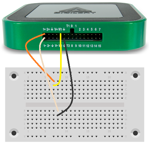
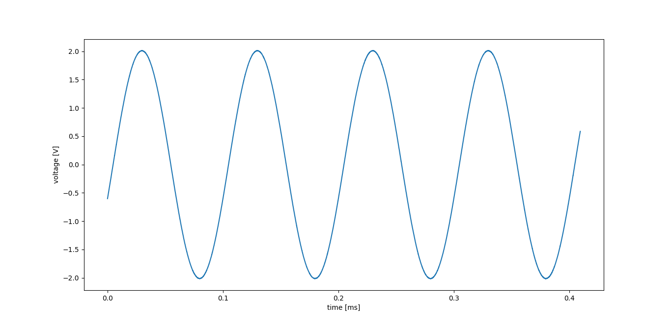
from WF_SDK import device, scope, wavegen   # import instruments

import matplotlib.pyplot as plt   # needed for plotting

"""-----------------------------------------------------------------------"""

# connect to the device
device_data = device.open()

"""-----------------------------------"""

# initialize the scope with default settings
scope.open(device_data)

# generate a 10KHz sine signal with 2V amplitude on channel 1
wavegen.generate(device_data, channel=1, function=wavegen.function.sine, offset=0, frequency=10e03, amplitude=2)

# record data with the scopeon channel 1
buffer, time = scope.record(device_data, channel=1)

# plot
time = [moment * 1e03 for moment in time]   # convert time to ms
plt.plot(time, buffer)
plt.xlabel("time [ms]")
plt.ylabel("voltage [V]")
plt.show()

# reset the scope
scope.close(device_data)

# reset the wavegen
wavegen.close(device_data)

"""-----------------------------------"""

# close the connection
device.close(device_data)


- Using the Logic Analyzer and the Pattern Generator
-
This example generates a PWM signal on a DIO line and reads it back with the logic analyzer. As the same line is used both as input and as output, no external connections have to be made.
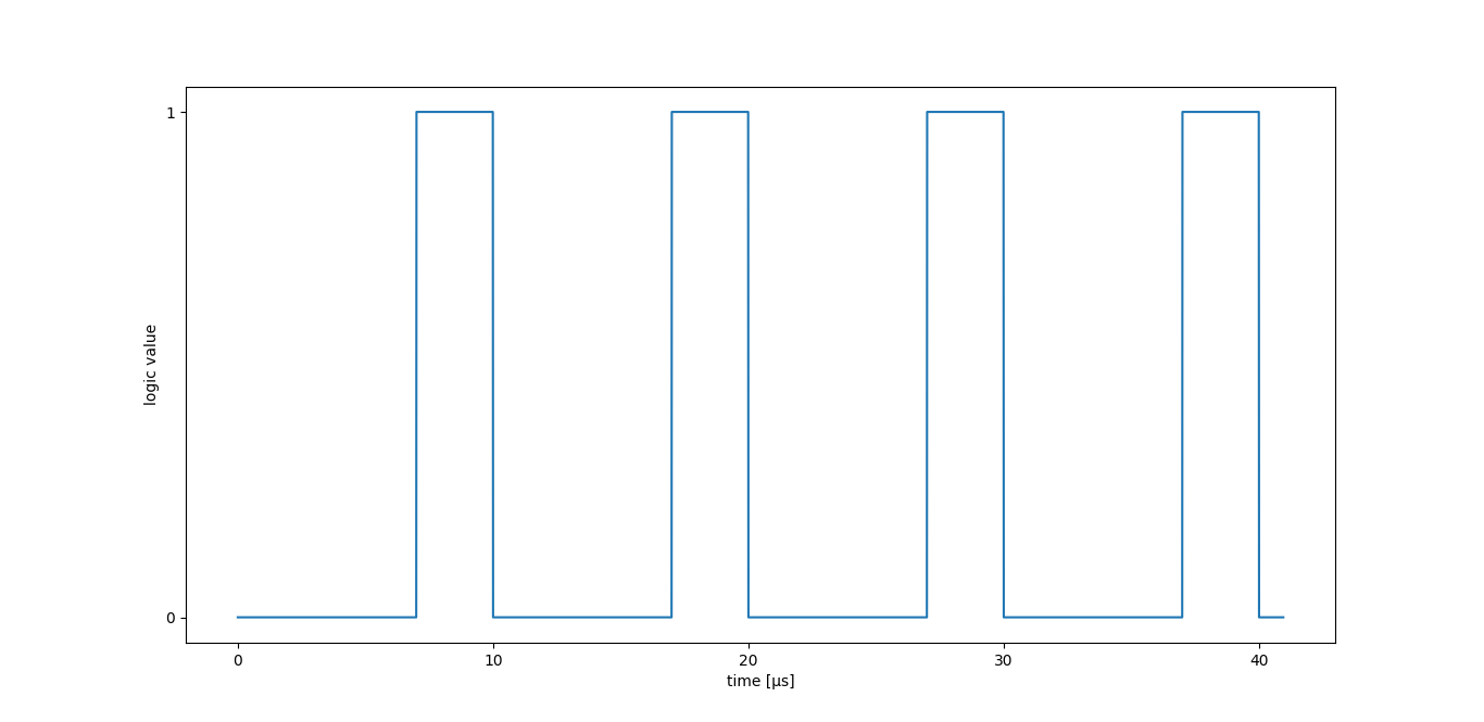
from WF_SDK import device, logic, pattern   # import instruments

import matplotlib.pyplot as plt   # needed for plotting

"""-----------------------------------------------------------------------"""

# connect to the device
device_data = device.open()

"""-----------------------------------"""

# initialize the logic analyzer with default settings
logic.open(device_data)

# generate a 100KHz PWM signal with 30% duty cycle on DIO0
pattern.generate(device_data, channel=0, function=pattern.function.pulse, frequency=100e03, duty_cycle=30)

# record a logic signal on DIO0
buffer, time = logic.record(device_data, channel=0)

# plot
time = [moment * 1e06 for moment in time]   # convert time to μs
plt.plot(time, buffer)
plt.xlabel("time [μs]")
plt.ylabel("logic value")
plt.yticks([0, 1])
plt.show()

# reset the logic analyzer
logic.close(device_data)

# reset the pattern generator
pattern.close(device_data)

"""-----------------------------------"""

# close the connection
device.close(device_data)

- Using the Static I/O and the Power Supplies
-
Connect LEDs and series resistors to each DIO channel of your device. Use the positive, or the digital power supply to provide current to the LEDs, then use the Static I/O instrument to sink the currents (turn the LEDs on/off).
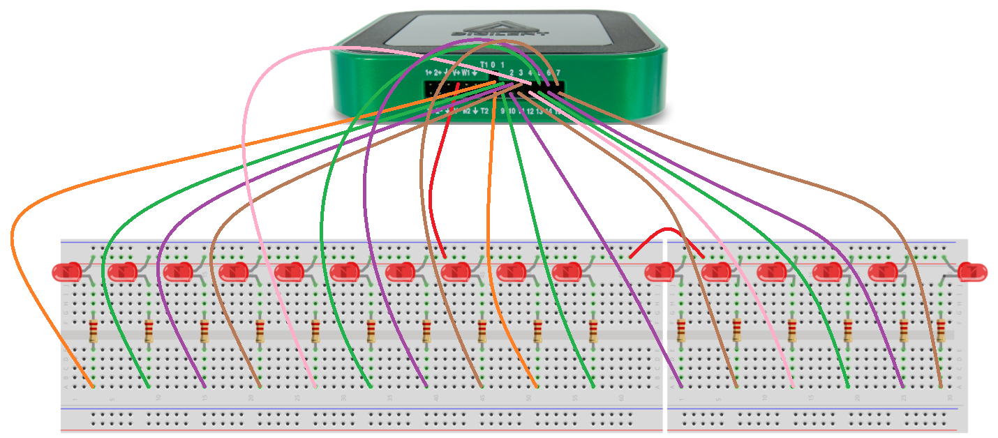
from WF_SDK import device, static, supplies       # import instruments

from time import sleep                            # needed for delays

device_name = "Analog Discovery 3"

"""-----------------------------------------------------------------------"""

# connect to the device
device_data = device.open()
device_data.name = device_name

"""-----------------------------------"""

# start the positive supply
supplies_data = supplies.data()
supplies_data.master_state = True
supplies_data.state = True
supplies_data.voltage = 3.3
supplies.switch(device_data, supplies_data)

# set all pins as output
for index in range(16):
    static.set_mode(device_data, index, True)

try:
    while True:
        # repeat
        mask = 1
        while mask < 0x10000:
            # go through possible states
            for index in range(16):
                # set the state of every DIO channel
                static.set_state(device_data, index, not(mask & pow(2, index)))
            sleep(0.1)  # delay
            mask <<= 1  # switch mask

        while mask > 1:
            # go through possible states backward
            mask >>= 1  # switch mask
            for index in range(16):
                # set the state of every DIO channel
                static.set_state(device_data, index, not(mask & pow(2, index)))
            sleep(0.1)  # delay

except KeyboardInterrupt:
    # stop if Ctrl+C is pressed
    pass

finally:
    # stop the static I/O
    static.close(device_data)

    # stop and reset the power supplies
    supplies_data.master_state = False
    supplies.switch(device_data, supplies_data)
    supplies.close(device_data)

    """-----------------------------------"""

    # close the connection
    device.close(device_data)

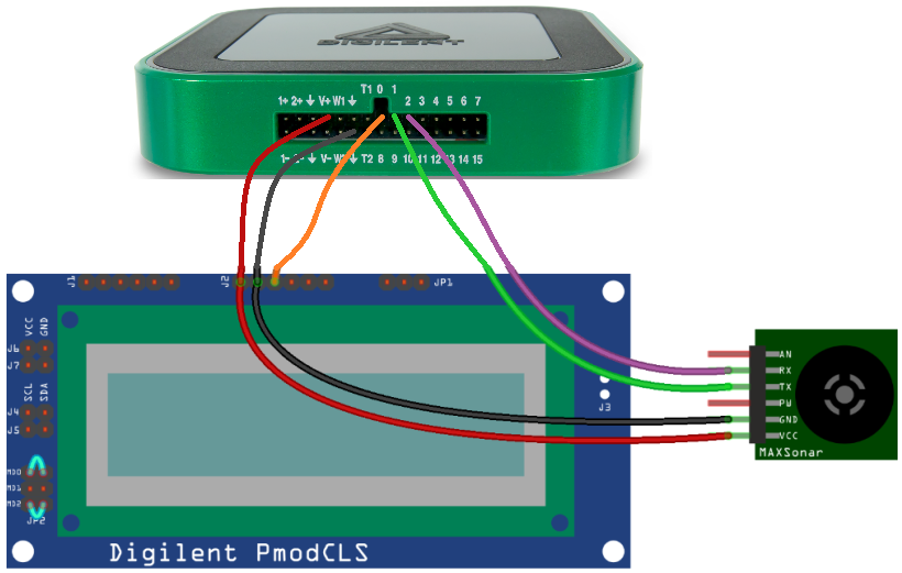
- Controlling the Pmod CLS and the Pmod MAXSonar with UART
-
Connect the UART interface of both Pmods to your Test & Measurement device as presented below. Pay special attention to the jumpers on the Pmod CLS. Use the positive, or the digital power supply to provide current to the Pmods, then receive and send data with the protocol instrument.
from WF_SDK import device, supplies, static     # import instruments
from WF_SDK.protocol import uart                # import protocol instrument

from time import sleep          # needed for delays

device_name = "Analog Discovery 3"

"""-----------------------------------------------------------------------"""

# connect to the device
device_data = device.open()
device_data.name = device_name

"""-----------------------------------"""

# define MAXSonar reset line
reset = 2

# define timeout iteration count
timeout = 1000

# start the power supplies
supplies_data = supplies.data()
supplies_data.master_state = True
supplies_data.state = True
supplies_data.voltage = 3.3
supplies.switch(device_data, supplies_data)
sleep(0.1)    # delay

# initialize the reset line
static.set_mode(device_data, reset, output=True)
static.set_state(device_data, reset, False)

# initialize the uart interface on DIO0 and DIO1
uart.open(device_data, tx=0, rx=1, baud_rate=9600)

try:
    # repeat
    while True:
        # clear the screen and home cursor
        uart.write(device_data, "\x1b[j")

        # display a message
        uart.write(device_data, "Dist: ")

        # read raw data
        static.set_state(device_data, reset, True)    # enable the device
        message = ""
        for _ in range(timeout):
            # wait for data
            message, error = uart.read(device_data)
            if message != "":
                # exit when data is received
                break
        static.set_state(device_data, reset, False)    # disable the device

        # convert raw data into distance
        try:
            if message[0] == 234:
                message.pop(0)    # remove first byte
                value = 0
                for element in message:
                    if element > 47 and element < 58:
                        # concatenate valid bytes
                        value = value * 10 + (element - 48)
                value *= 2.54   # convert to cm
        except:
            # error in message
            value = -1

        # display the distance
        uart.write(device_data, str(round(value, 2)))

        # display a message
        uart.write(device_data, "cm")

        # delay 1s
        sleep(1)

except KeyboardInterrupt:
    # exit on Ctrl+C
    pass

# reset the interface
uart.close(device_data)

# reset the static I/O
static.set_mode(device_data, reset, output=False)
static.set_state(device_data, reset, True)
static.close(device_data)

# stop and reset the power supplies
supplies_data.master_state = False
supplies.switch(device_data, supplies_data)
supplies.close(device_data)

"""-----------------------------------"""

# close the connection
device.close(device_data)

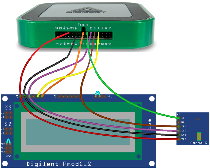
- Controlling the Pmod CLS and the Pmod ALS with SPI
-
Connect the SPI interface of both Pmods to your Test & Measurement device as presented below. Pay special attention to the jumpers on the Pmod CLS. Use the positive, or the digital power supply to provide current to the Pmods, then receive and send data with the protocol instrument.
from WF_SDK import device, supplies     # import instruments
from WF_SDK.protocol import spi         # import protocol instrument

from time import sleep          # needed for delays

device_name = "Analog Discovery 3"

"""-----------------------------------------------------------------------"""

# connect to the device
device_data = device.open()
device_data.name = device_name

"""-----------------------------------"""

# define chip select lines
CLS_cs = 0
ALS_cs = 1

# start the power supplies
supplies_data = supplies.data()
supplies_data.master_state = True
supplies_data.state = True
supplies_data.voltage = 3.3
supplies.switch(device_data, supplies_data)

# initialize the spi interface on DIO0, DIO1, DIO2, DIO3 and DIO4
spi.open(device_data, CLS_cs, sck=2, miso=3, mosi=4)
spi.open(device_data, ALS_cs, sck=2, miso=3, mosi=4)

try:
    # repeat
    while True:
        # clear the screen and home cursor
        spi.write(device_data, "\x1b[j", CLS_cs)

        # display a message
        spi.write(device_data, "Lum: ", CLS_cs)

        # read the temperature
        message = spi.read(device_data, 2, ALS_cs)
        value = ((int(message[0]) << 3) | (int(message[1]) >> 4)) / 1.27

        # display the temperature
        spi.write(device_data, str(round(value, 2)), CLS_cs)

        # display a message
        spi.write(device_data, "%", CLS_cs)

        # delay 1s
        sleep(1)

except KeyboardInterrupt:
    # exit on Ctrl+C
    pass

# reset the interface
spi.close(device_data)

# stop and reset the power supplies
supplies_data.master_state = False
supplies.switch(device_data, supplies_data)
supplies.close(device_data)

"""-----------------------------------"""

# close the connection
device.close(device_data)

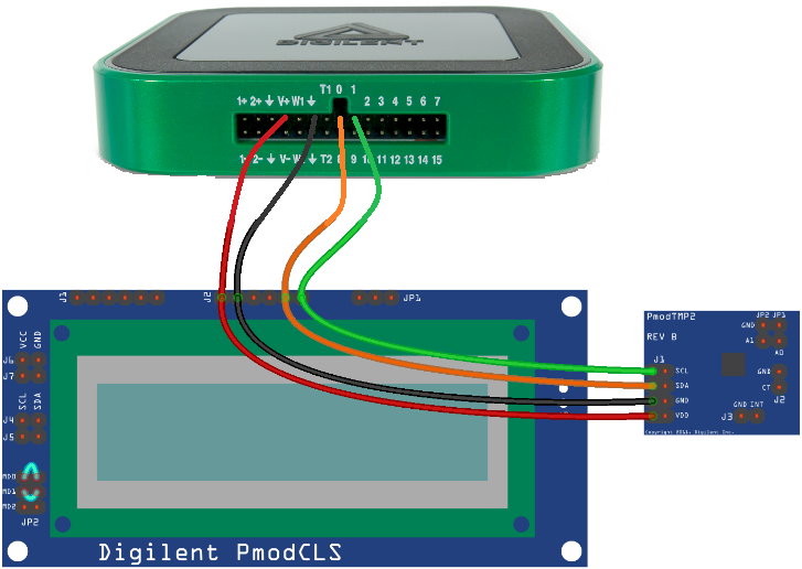
- Controlling the Pmod CLS and the Pmod TMP2 with I2C
-
Connect the I2C interface of both Pmods to your Test & Measurement device as presented below. Pay special attention to the jumpers on the Pmod CLS. Use the positive, or the digital power supply to provide current to the Pmods, then receive and send data with the protocol instrument.
from WF_SDK import device, supplies     # import instruments
from WF_SDK.protocol import i2c         # import protocol instrument

from time import sleep          # needed for delays

device_name = "Analog Discovery 3"

"""-----------------------------------------------------------------------"""

# connect to the device
device_data = device.open()
device_data.name = device_name

"""-----------------------------------"""

# define i2c addresses
CLS_address = 0x48
TMP2_address = 0x4B

# start the power supplies
supplies_data = supplies.data()
supplies_data.master_state = True
supplies_data.state = True
supplies_data.voltage = 3.3
supplies.switch(device_data, supplies_data)
sleep(0.1)    # delay

# initialize the i2c interface on DIO0 and DIO1
i2c.open(device_data, sda=0, scl=1)

# initialize the PMOD TMP2 (set output size to 16-bit)
i2c.write(device_data, [0x03, 0x80], TMP2_address)

# save custom character
i2c.write(device_data, "\x1b[7;5;7;0;0;0;0;0;0d", CLS_address)   # define character
i2c.write(device_data, "\x1b[3p", CLS_address) # load character table

try:
    # repeat
    while True:
        # clear the screen and home cursor
        i2c.write(device_data, [0x1B, 0x5B, 0x6A], CLS_address)

        # display a message
        i2c.write(device_data, "Temp: ", CLS_address)

        # read the temperature
        message, error = i2c.read(device_data, 2, TMP2_address)   # read 2 bytes
        value = (int(message[0]) << 8) | int(message[1])    # create integer from received bytes
        if ((value >> 15) & 1) == 0:
            value /= 128    # decode positive numbers
        else:
            value = (value - 65535) / 128   # decode negative numbers

        # display the temperature
        i2c.write(device_data, str(round(value, 2)), CLS_address)

        # display a message
        i2c.write(device_data, 0, CLS_address)
        i2c.write(device_data, "C", CLS_address)

        # delay 1s
        sleep(1)

except KeyboardInterrupt:
    # exit on Ctrl+C
    pass

# reset the interface
i2c.close(device_data)

# stop and reset the power supplies
supplies_data.master_state = False
supplies.switch(device_data, supplies_data)
supplies.close(device_data)

"""-----------------------------------"""

# close the connection
device.close(device_data)

Installing the Package
Once you completed the package, you might want to install it, like other Python packages and use it on new projects as well. To do so, you must create some additional files in the project folder.
First, exclude the test scripts from the final package. Create a file named MANIFEST.in, with the content:
global-exclude test_*
The installer needs the list of dependencies to install your package. Specify this list on a file called requirements.txt:
setuptools==58.1.0
wheel==0.37.1
Finally, create a README.md file with the description of your package, then create the installer. The installer is the file named setup.py, with the following content:
from setuptools import setup

with open("README.md", "r") as f:
    long_description = f.read()

setup(
   name = "WF_SDK",
   version = "1.0",
   description = "This module realizes communication with Digilent Test & Measurement devices",
   license = "MIT",
   long_description = long_description,
   author = "author_name",
   author_email = "author_email_address",
   url = "https://digilent.com/reference/test-and-measurement/guides/waveforms-sdk-getting-started",
   packages = ["WF_SDK", "WF_SDK.protocol"],
)
Once the necessary files are created, open a terminal, go to the project folder and install your package with the following command:
pip3 install .
Alternatively, you can install the package from the GitHub repository, with the command:
pip3 install git+https://github.com/Digilent/WaveForms-SDK-Getting-Started-PY#egg=WF_SDK
If you already installed the package, you can update it with the command:
pip3 install --force-reinstall git+https://github.com/Digilent/WaveForms-SDK-Getting-Started-PY#egg=WF_SDK
Note: Use “pip” instead of “pip3”, if you are using Python 2.
Other Programming Languages
Realizing the same package in other programming languages is also possible. To check the C++ version of the package and some test programs, follow this GitHub repository, C++ link.
Next Steps
For more guides on how to use your Digilent Test & Measurement Device, return to the device's Resource Center, linked from the Test and Measurement page of this wiki.
For more information on the WaveForms SDK visit the WaveForms SDK Resource Center.
For more information on WaveForms visit the WaveForms Reference Manual.
For technical support, please visit the Test and Measurement section of the Digilent Forums.