WaveForms Live Reference Manual
Despite our hopes and effort to create an innovative and low-cost T&M solution, we’ve received consistent negative feedback on the OpenScope MZ and OpenLogger regarding overall reliability that has led us to determine that it is not up to our high standards for our test and measurement products.
Unfortunately, we are unable to fix many of the issues, so we have made the difficult decision to pull both products, and related accessories from our shelves. This will allow us to ensure we can continue to deliver on the Digilent brand promise and focus our efforts on expanding our popular and core line of Test and Measurement Products.
The materials on this page will remain here as legacy sources. Any Digilent provided support for this material will be extremely limited at best. Thank you for understanding.
WaveForms Live makes it easy to control and interact with instrumentation hardware by providing a cross platform graphical user interface that combines support for an oscilloscope, logic analyzer, GPIO, power supply and more into a single application.
WaveForms live is free and open source. Try it now at WaveFormsLive.com.

Overview
WaveForms live is available as a hosted browser app at WaveFormsLive.com, as an 'offline' browser app as part of the Digilent Agent, and as a native app for Windows, Mac, Linux, Android and iOS.
The browser based version of WaveForms Live at WaveFormsLive.com is recommended as it will include the latest features and bug fixes.
WaveForms Live is open source and built on Ionic 2 and Angular2 and written in TypeScript, HTML and CSS. The source code is available on GitHub.
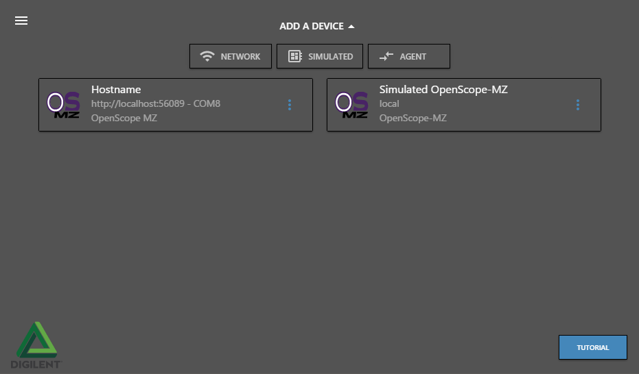
Device Manager
WaveForms Live displays the device manager on launch. The device manager allows users to manage and configure WaveForms Live compatible devices. Devices added to the device manager will be stored locally (using in browser or in app cache).
- Menu - Toggle the side menu open/closed.
- Add A Device - Click to add a new device to the device manager.
- Device Card - A card representing a device or agent. Click the card to go to the default instrument panel for the device.
- Firmware Update Available - Indicates that new firmware is available for the device. Click to start the firmware update process.
- Device Info - Information about the device. The fields displayed depend on the device type.
- More - Click to view device options.
- Digilent Logo - The Digilent logo.
- Tutorial - Click to enable tutorial mode. Tutorial mode provides a interactive walk through of WaveForms Live using a simulated device.

Add A Device
The add device drop down enables users to add new devices to WaveForms Live. Three device types are supported: Network, Simulated, and Agent.
- A simulated device is a pure software device that is designed to provide a way to test the WaveForms Live software without additional hardware.
- A network device is a WaveForms Live compatible devices that is available on the local network (ex. an OpenScope MZ on the local Wifi network).
- The Digilent Agent is a service that runs in the system tray on Windows, Mac and Linux and enables browser based applications like Waveforms Live to communicate with Digilent hardware. Using the Digilent Agent to connect to a device connected to the computer via USB offers several advantages including the ability to update the device firmware and setup Wifi. The Agent must be configured using WaveForms Live to set the active device before use.
- Add A Device - Click to add a new device to WaveForms Live.
- Network - Add a WaveForms Live compatible device on the local network.
- Simulated - Add a software simulated device. This is useful for exploring WaveForms Live without additional hardware.
- Hostname / IP - Specify the hostname or IP address of the network device.
- Cancel - Cancel without adding a new device.
- Add - Add the specified device.
- Simulated Device Type - The type of device to simulate.
- Digilent Agent - The hostname or IP and port of the Digilent Agent to add. The default value http://localhost:42135 matches the default Digilent Agent settings. The Agent must be available on the network or local machine.

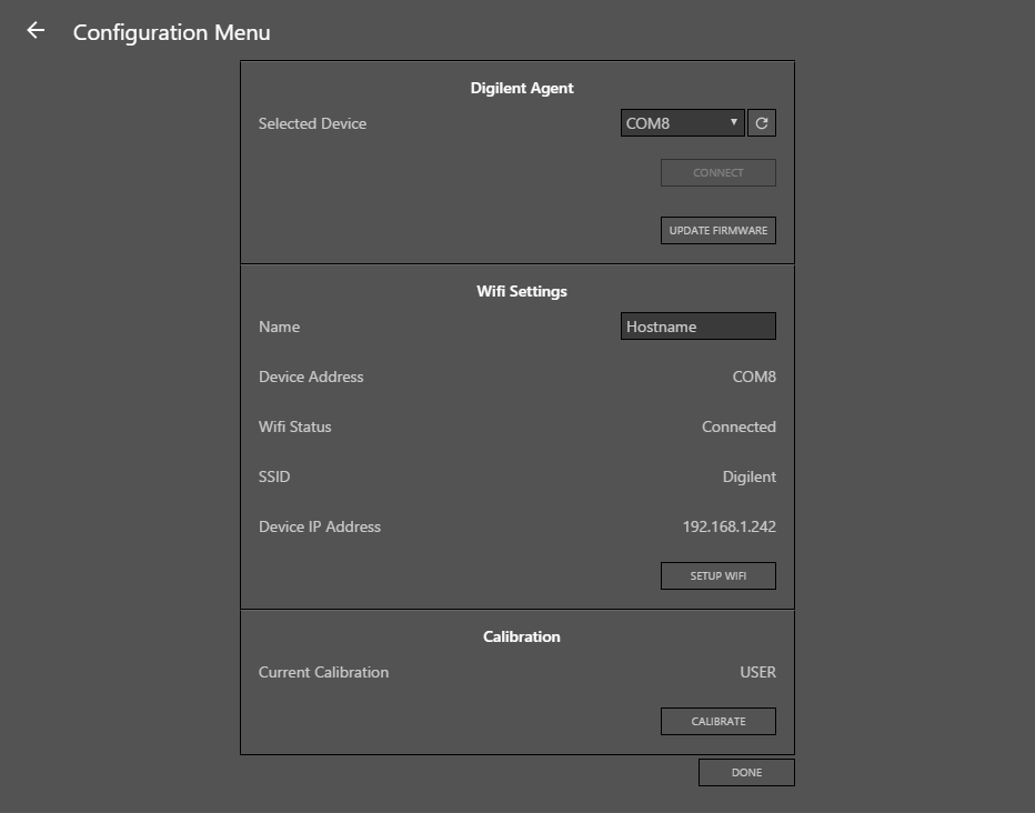
Device Configuration
The device configuration menu provides access to configure device settings including calibration, network settings and configure the Digilent Agent. The Agent section is only available configuring a Digilent Agent.
- Agent Active Device - The hardware device that the Agent should use.
- Refresh - Refresh the list of hardware devices.
- Connect - Connect to and enumerate the selected device.
- Update Firmware - Update the firmware on the selected device. This button launches the Update Firmware Wizard.
- Name - The device hostname.
- Device Address - The address currently being used to communicate with the device. This may be a COM port or IP address depending on the device type.
- Wifi Status - Indicates the status of the device's Wifi connection.
- SSID - Indicates the selected SSID.
- Device IP Address - Indicates the IP address of the device or 0.0.0.0 if the device is not connected to a Wifi network.
- Setup Wifi - Launch the setup wifi wizard to configure the device's wifi settings.
- Current Calibration - Indicates the current calibration profile applied to the instruments.
- Calibrate - Launch the device calibration wizard to calibrate the device.
- Done - Save changes and return to the device manager.

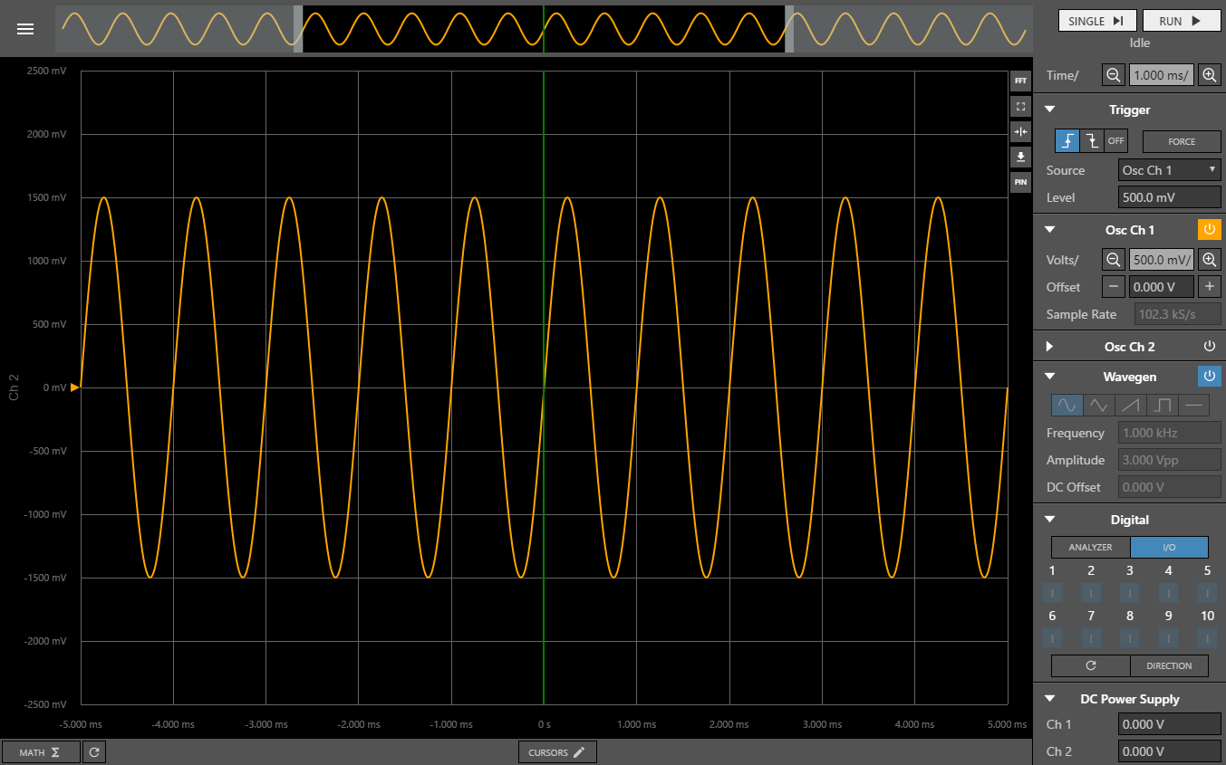
Instrument Panel
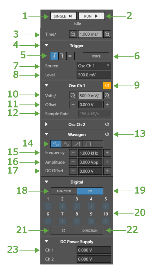
The instrument panel provides access to core device functionality and enables the user to configure the triggers, oscilloscope, wavegen, logic analyzer, gpio, and power supplies, manipulate the cart, acquire samples and more.
- Single - Perform a single-shot acquisition. Clicking this button will arm the trigger and return a single buffer of data once the acquisition completes.
- Run - Clicking this button will arm the trigger. When the acquisition completes and the device is in run mode a buffer of data is returned and the trigger is automatically re-armed.
- Time/ - The time per division of the chart's X-axis.
- Expand / Collapse - Click to expand or collapse the control panel section.
- Trigger Mode - The trigger mode. From left to right: Rising, Falling, Off.
- Force Trigger - If the trigger is armed this button forces the trigger condition and returns a buffer of data once the acquisition is complete. If the trigger is not armed this button has no effect.
- Source - The trigger source.
- Level - The trigger threshold level.
- Enable Button - Toggle the oscilloscope channel on / off.
- Volts/ - The volts per division on the Y-Axis of the chart.
Note: Each oscilloscope and logic analyzer channel has it's own independent Y axis.
- Offset - The Y-Axis offset of the specified channel.
- Sample Rate - The rate at which the oscilloscope channel will be sampled.
Note: This value is read only be default and is updated based on the chart zoom.
- Enable - Toggle the wavegen on/off.
- Wave Type - The regular waveform output type. From left to right: sine, triangle, sawtooth, square, dc.
- Frequecy - The frequency of the periodic regular waveform.
- Amplitude - The peak-to-peak amplitude of the waveform.
- DC Offset - The DC offset of the waveform.
- Analyzer - Select digital pins to use as logic analyzer inputs.
- I/O - Set output values of digital outputs and display input values of pins configured as digital inputs.
- Digital Channels - The digital channels.
- Digital channels configured as logic analyzer channels are indicated with a green background and A.
- Digital channels configured as inputs are indicated with a blue background and an I.
- Digital channels configured as outputs are indicated with a blue background, black outline, and an O.
- Digital inputs and output channels are dull when at a logic low value and bright when at a logic high value.
- Refresh - Read the digital input values and update the display.
- Direction - Set digital channel directions as input or output.
- Ch1 - DC Supply Channel 1 value.
Note: After setting a new value the actual achieved value will be displayed
Chart
The instrument panel chart is used to display oscilloscope, and logic analyzer signal data. The x-axis (time) is shared between all channels, however, each channels has it's own independent y-axis.
- Timeline - Displays the full buffer with shaded areas indicating the portion of the buffer that is visible in the chart.
- FFT - Click to display the fast fourier transform chart for the current oscilloscope data buffer.
- Auto Scale - Auto scale the X and Y axis to fit all points in the chart view.
- Center On Trigger - Center the current view on the trigger.
- Export - Export the current buffer as a .png or .csv file.
- Pin - Display the device pinout.
- Channel Anchor - Indicates the center of the sampled range. Click and drag to vertically pan the signal.
- Active Channel - Indicates the active channel. Y-axis units adapt to the active channel.
- Trigger - Indicates the trigger location in the buffer.
- Math - Provides access to enable and disable math functions like frequency and amplitude measurements.
- Refresh Math - Update the calculated 'math' values.
- Cursors - Enable/disable and configure cursors.

Update Firmware
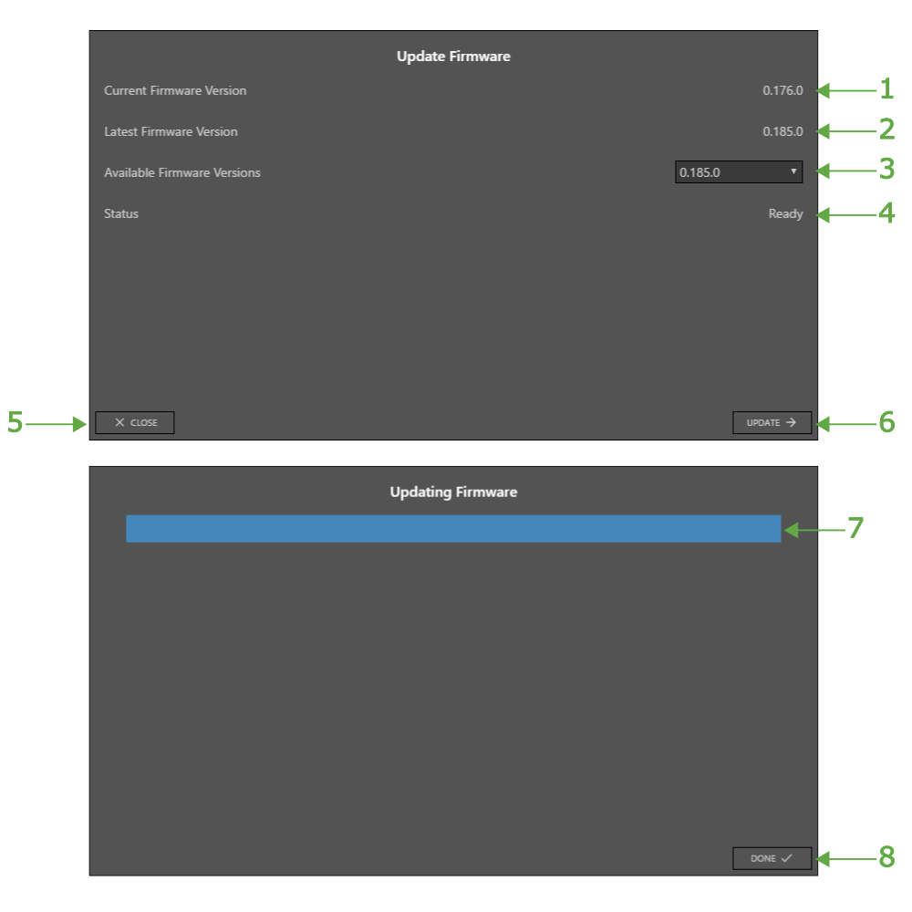
The update firmware wizard enables users to update or change the firmware on WaveForms Live compatible devices. Firmware can be pulled from the online repository or selected from the host PC.
Note: It is only possible to update OpenScope MZ firmware when connected to the device using the Digilent Agent
- Current Firmware Version - Indicates the version of the firmware running on the device.
- Latest Firmware Version - Indicates the most recent firmware version available in online the firmware repository.
- Available Firmware Versions - Select the desired firmware version from the repository or Other to browser for a local firmware file.
- Status - Indicates the status of the firmware update or lists errors.
- Close - Cancel the firmware update and close the wizard.
- Update - Start the firmware update process.
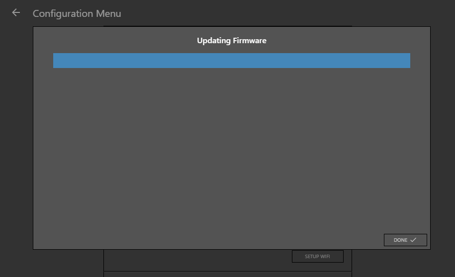
- Progress - Indicates the progress of the firmware updated.
- Done - Available once the firmware update process is complete. Click to close the firmware update wizard.
Calibration
The calibration wizard enables users to calibrate the instruments, save calibration data and load previously saved calibration data.
- Instructions - Device specific instructions that describe how to configure the device for calibration.
- Close - Cancel device calibration and close the wizard.
- Load Existing - Load existing calibration data and apply it to the instruments.
- Begin - Start the calibration process.
- Progress - The calibration progress.
- Calibration Data - The new calibration data.
- Storage Location - The storage location on the device to store the calibration data.
- Refresh - Refresh the storage location list.
- Save - Save the calibration data to the specified storage location.
- Status - Indicates the status of the calibration process.
- Done - Close the calibration wizard.
- Storage Location - The storage location on the device to load calibration data from.
- Refresh - Refresh the storage location list.
- Load - Load calibration data from the specified location and apply it to the instruments. Calibration data is also displayed in WaveForms Live.
- Calibration Data - The loaded calibration data.
- Status - Indicates the status of the load calibration process.
- Done - Close the calibration wizard.

Wifi Setup
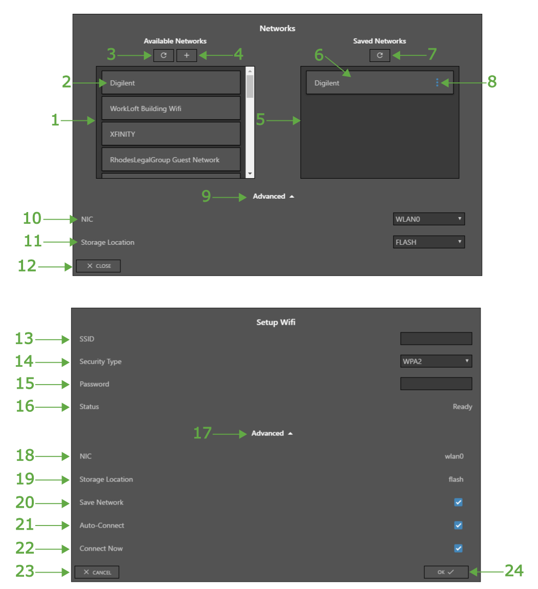
The Wifi setup wizard enables users to configure the device's wifi settings by scanning for networks, entering security credentials and saving network configurations.
- Scan Networks - Scan for available wifi networks.
- Add Network - Add a wifi network by manually entering the SSID and security settings.
- Saved Network - A saved network configuration.
- Refresh Saved Networks - Refresh the list of saved networks from the device.
- Available Network - An available network found during the previous wifi scan.
- Saved Network More - Show configuration options for the saved network.
- Available Networks - Displays all available networks found during the previous wifi scan.
- Saved Networks - Displays network configurations saved on the device.
- Advanced - Show / hide advanced settings.
- NIC - The network interface controller to use.
- Storage Location - The on-device storage location to read/write network configuration data.
- Close - Close the wifi configuration wizard.
- SSID - The Wifi network name (service set identifier).
- Security Type - The network security type.
- Password - The network password. This field adapts to the security type. For example for a network with WEP104 encryption this field would adapt to WEP key inputs.
- Status - Indicates the network adapter status.
- Advanced - Show / hide advanced settings.
- NIC - Indicates the network interface controller that will be used.
- Storage Location - Indicates where the network configuration will be saved.
- Save Network - If checked the network configuration will be saved to the specified storage location. If not checked the network configuration data will not be saved.
- Auto-Connect - If checked the device will attempt to automatically connect to this network on boot.
- Connect Now - If checked the device will attempt to connect to the network when 'OK' is clicked.
- Cancel - Discard changes and close the wizard.
- OK - Save changes and close the wizard.
WaveForms Live Settings
The WaveForms Live settings page provides application wide configuration options and information.
- Chart Hotkeys - Hotkeys available on the instrument panel chart.
- Advanced - Show / hide advanced settings.
- Change Logging Behavior - Select the location to store log data.
- Export Log - Export stored log data to a text file.
- Clear Local App Log - Clear all stored log data.
- Use Dev Firmware Builds - If enabled, pre-release development firmware builds will be available in the update firmware wizard.
- WaveForms Live Version - WaveForms Live version information.

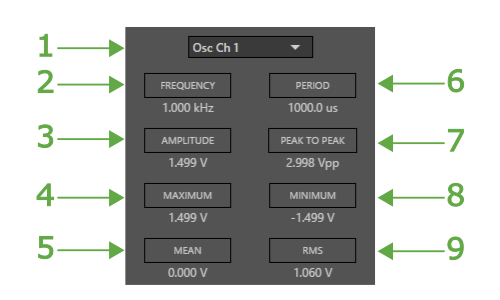
Math
The math menu allows users to enable and disable various automatic calculations like signal frequency, amplitude, etc.
- Channel - The input channel to use as the signal source for the operation.
- Frequency - Calculate the frequency of a periodic signal.
- Amplitude - Calculate the amplitude of the signal.
- Maximum - Calculate the maximum value of the signal.
- Mean - Calculate the mean value of the signal.
- Period - Calculate the period of a periodic signal.
- Peak to Peak - Calculate the peak-to-peak voltage of the signal.
- Minimum - Calculate the minimum value of the signal.
- RMS - Calculate the Root Mean Square of the signal.
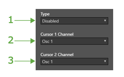
Cursors
The cursors window allows users to enable and configure cursors on the chart. Cursors can be used to measure time, signal values and differences between points.
- Type - The cursor type: Time, Track or Voltage.
- Cursor 1 - The channel to attach cursor 1.
- Cursor 2 - The channel to attach cursor 2
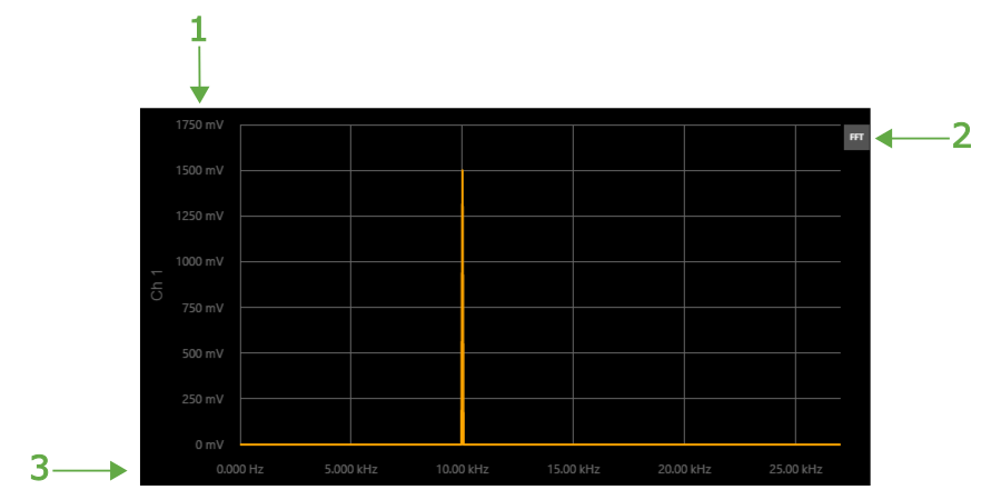
FFT
The FFT window displays the fast Fourier transform of the current buffer.
- X-Axis - FFT Amplitude.
- FFT - Toggle FFT mode on / off.
- Y-Axis - Frequency.
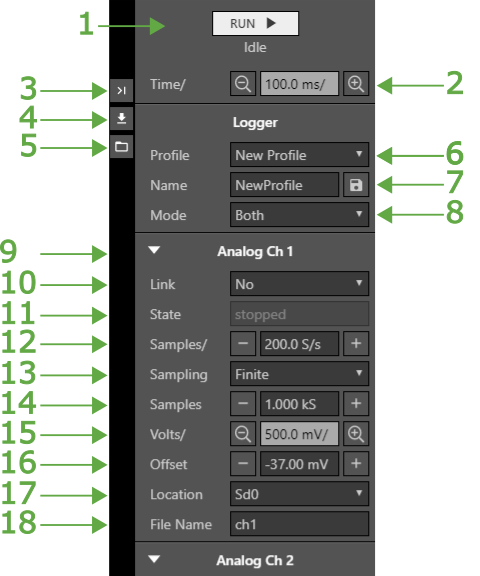
Logger Page
The logger page provides access to core logger functionality and enables the user to create and load logging profiles, set sampling parameters, start a logging session, stream data to the chart, manipulate the cart, export chart data as a csv, and more.
- Log / Stream / Run - Click to start a logging session. See the “Mode” section for a more in-depth explanation.
- Time/ - The time per division of the chart's X-axis.
- Snap To Front - Click to snap view to latest data.
- Export - Click to export chart data as CSV or PNG.
- File Browser - Click to open the file browser modal.
- Profile - Create or load profiles. If “New Profile” is selected, the “Name” input is revealed. Previously saved profiles will be listed in the Profile drop-down.
- Save Button - Clicking the save button will save the current logging parameters to the device and will select that profile.
- Mode - The desired mode for a logging session. If the selected mode is “Log”, the device will start logging without streaming data to WaveForms Live. If the selected mode is “Stream”, the device will only stream data to WaveForms Live and display it. If the selected mode is “Both”, the device will start a log file and simultaneously stream data to WaveForms Live and display it on the chart.
- Expand / Collapse - Click to expand or collapse the control panel section.
- Link - Linking refers to copying the same parameters from another channel. For example, if Analog Ch 2 is linked to Analog Ch 1, Analog Ch 2 will have the same settings as Ch 1. “State” and “File Name” will still remain independent since log files must have different names and all channel states are independent.
- State - The state of the channel. Options are: idle, stopped, busy.
- Samples/ - The sampling rate to be used.
- Sampling - The sampling style to be used. Options are: Continuous or Discrete. Continuous keeps sampling until the user clicks stop. Discrete samples for a specific number of samples.
- Samples - The number of samples to acquire.
- Volts/ - The volts per division on the Y-Axis of the chart.
- Offset - The Y-Axis offset of the specified channel.
- Location - The location to save the log file.
- File Name - The name of the log file created.