Pmod RF2 Reference Manual
Please note: the Pmod RF2 is no longer in production. Once the current stock is depleted, it will be retired.
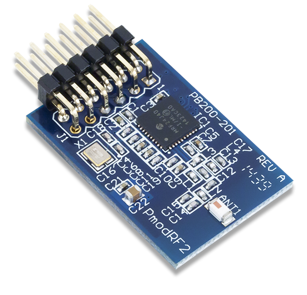
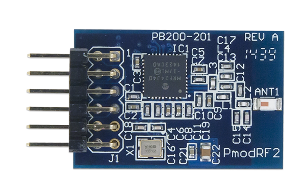
The Pmod RF2 adds RF communication through the Microchip® MRF24J40 IEEE 802.15.4™ 2.4GHz RF transceiver module. By communicating with the device through SPI, users can transmit data at speeds up to 625 kbps through the ZigBee®, MiWi™, and MiWi P2P software stacks all available for download at the Microchip website: www.microchip.com/wireless.
Features
- IEEE 802.15-compliant RF transceiver
- Supports ZigBee, MiWi and MiWi P2P wireless networking protocols
- ISM band 2.405-2.48 GHz operation
- Integrated 20 MHz and 32.768 oscillator circuitry
- 12-pin Pmod connector with SPI interface
- Follows Digilent Pmod Interface Specification Type 2A
Functional Description
The Pmod RF2 adds RF communication through the Microchip® MRF24J40 IEEE 802.15.4™ 2.4GHz RF transceiver module. By communicating with the device through SPI, users can transmit data at speeds up to 625 kbps through the ZigBee®, MiWi™, and MiWi P2P software stacks all available for download at the Microchip website: www.microchip.com/wireless.
Interfacing with the Pmod
The Pmod RF2 communicates with the host board via the SPI protocol. The host system board will communicate with the Pmod RF2 in SPI Mode 0. An active low RST pin pin 8 is available for the host board to issue a hardware reset to the Pmod RF2. A polarity configurable interrupt pin pin 7, is there to allow the Pmod RF2 to signal to the host board when there is data available for the host device. The interrupt pin will be de-asserted by the module after the INTSTAT register is read.
Pinout Description Table
| Pin | Signal | Description | Pin | Signal | Description |
|---|---|---|---|---|---|
| 1 | ~CS | Chip Select | 7 | INT | Interrupt |
| 2 | MOSI | Master-Out-Slave-In | 8 | ~RST | Hardware Reset |
| 3 | MISO | Master-In-Slave-Out | 9 | WAKE | Hardware Wake |
| 4 | SCLK | Serial Clock | 10 | NC | Not Connected |
| 5 | GND | Power Supply Ground | 11 | GND | Power Supply Ground |
| 6 | VCC | Power Supply (3.3V) | 12 | VCC | Power Supply (3.3V) |
Any external power applied to the Pmod RF2 must be within 2.7V and 3.6V; however, it is recommended that Pmod is operated at 3.3V.
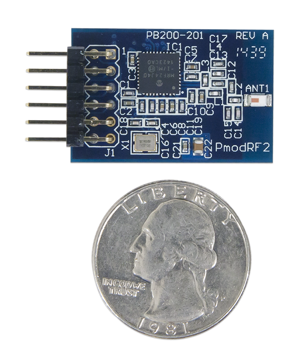
Physical Dimensions
The pins on the pin header are spaced 100 mil apart. The PCB is 1.2 inches long on the sides parallel to the pins on the pin header and 0.8 inches long on the sides perpendicular to the pin header.
Additional Information
You can consult the schematics of the PmodRF2 for more detailed information. To find out how to obtain information from the Pmod RF2, check the example code.
Additional information about the MRF24J40 including communication modes and specific timings of the chip can be found by checking out its datasheet.
If you have any questions or comments about the Pmod RF2, feel free to post them under the appropriate section (“Add-on Boards”) of the Digilent Forum.