Pmod DA3 Reference Manual
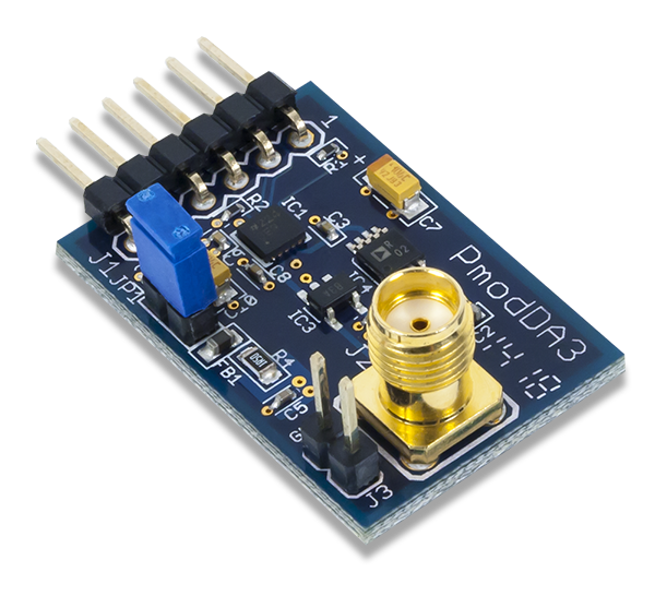
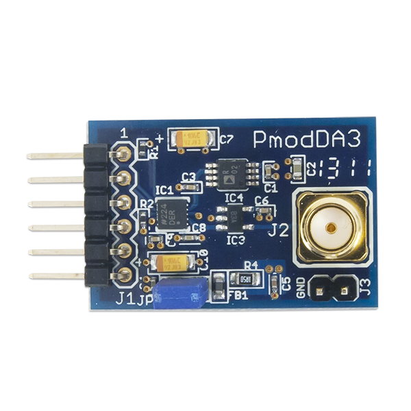
The Digilent Pmod DA3 (Revision B) is a 16-bit Digital-to-Analog converter with an SMA connector for high resolution and low noise analog output.
Download This Reference Manual
Features
- High resolution, 16-bit Digital-to-Analog converter
- Low noise analog output
- SMA connector
- 2.5V reference voltage
- 6-pin Pmod port with GPIO interface
- Follows Digilent Pmod Interface Specification Type 1
Functional Description
The Pmod DA3 utilizes Analog Devices AD5541A to provide analog output with 16-bit resolution.
Interfacing with the Pmod
The Pmod DA3 communicates with the host board via a SPI-like protocol. This interface is different than the traditional SPI protocol in the fact that the pin normally designated to the host receiving data (MISO), is now used for a Load DAC (LDAC) function so that the output of the DAC can be updated immediately once the module is loaded with the incoming 16 bits of data.
To send data to the Pmod, users must drive the Chip Select (CS) line to a logic level low voltage and then send the 16 clock pulses and 16 bits of data in SPI Mode 0; that is, placing the most significant bit (MSB) of data on the data line right after the Serial Clock line (SCLK) has been brought to a logic level low voltage.
When all of the data has been latched into, i.e. prepared for, the internal serial input register, bringing the CS line back to a logic level high voltage will transfer all of the data from the shift register to the serial input register if LDAC is at a high voltage state. Pulsing the LDAC pin low and then high will asynchronously transfer all of the data into the DAC register, resulting in the appropriate analog voltage on the SMA connector. Alternatively, users may hold the LDAC pin at a logic level low voltage when bringing the CS pin high to directly transfer the data from the shift register to the DAC register.
Pinout Description Table
| Pin | Signal | Description |
|---|---|---|
| 1 | ~CS | Chip Select |
| 2 | DIN | Data Input |
| 3 | ~LDAC | Load DAC |
| 4 | SCLK | Serial Clock |
| 5 | GND | Power Supply Ground |
| 6 | VCC | Power Supply (3.3V/5V) |
Any external power applied to the Pmod DA3 must be within 2.7V and 5.5V; however, it is recommended that Pmod is operated at 3.3V.
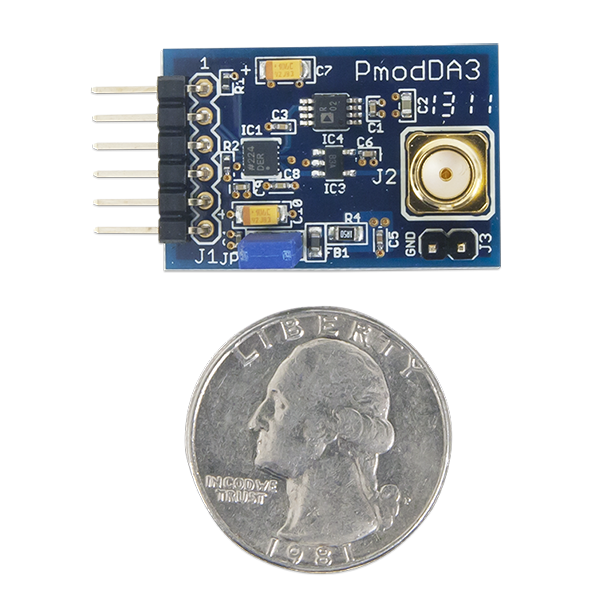
Physical Dimensions
The pins on the pin header are spaced 100 mil apart. The PCB is 1.2 inches long on the sides parallel to the pins on the pin header and 0.8 inches long on the sides perpendicular to the pin header.
Additional Information
The schematics of the Pmod DA3 are available here. Additional information about the DAC including communication modes and specific timings of the chip can be found by checking out its datasheet here.
Example code demonstrating how to get information from the Pmod DA3 can be found here.
If you have any questions or comments about the Pmod DA3, feel free to post them under the appropriate section (“Add-on Boards”) of the Digilent Forum.