Pmod BB Reference Manual
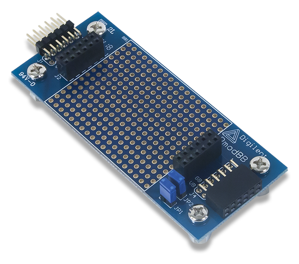
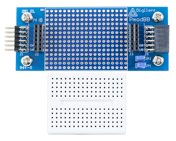
The Digilent Pmod BB (Revision A) is handy prototyping platform that can plug directly into a Pmod header on your system board. It has a 14×19 wire wrap surface as well as a 170 tie point solderless breadboard that can be snugly placed on top of the perfboard.
Download This Reference Manual
Features
- 266 tie point wire wrap area
- 170 tie point solderless breadboard
- Jumper blocks to tie the power pins together
- Additional Pmod host port
- 12-pin connector, all signals pass through
Functional Description
The Pmod BB is able to act as an intermediary module between the system board and external circuitry. This is useful if you need a small area to add a filter to process the incoming signals or a visual indicator showing the status or strength of the signals.
Interfacing with the Pmod
The Pmod BB is connected to the system board so that all of pins are pass through. Any specific protocol would be dependent on the circuitry placed on the module. The two jumper blocks, JP1 and JP2, tie the positive power and ground lines of both ends of the module together, respectively. Headers J2 and J3 are directly tied to the Pmod headers J1 and J4, respectively, for easy prototyping access.
The first and last column of 14 holes on the wire wrap surface each have two sets of seven holes to create mini-buses for the positive power supply and ground power supply of both ends of the Pmod BB.

A pinout table of the headers on the Pmod BB is provided below:
Pinout Description Table
| Headers J1 and J2 | Headers J3 and J4 | Jumper JP1 | |||||||
|---|---|---|---|---|---|---|---|---|---|
| Pin | Signal | Description | Pin | Signal | Description | State | Description | ||
| 1 | P1 | Pin 1 | 1 | P1 | Pin 1 | Loaded | VA and VB are tied together | ||
| 2 | P2 | Pin 2 | 2 | P2 | Pin 2 | Jumper JP2 | |||
| 3 | P3 | Pin 3 | 3 | P3 | Pin 3 | State | Description | ||
| 4 | P4 | Pin 4 | 4 | P4 | Pin 4 | Loaded | GA and GB are tied together | ||
| 5 | GA | Power Supply Ground | 5 | GB | Power Supply Ground | ||||
| 6 | VA | Power Supply (3.3V/5V) | 6 | VB | Power Supply (3.3V/5V) | ||||
| 7 | P7 | Pin 7 | 7 | P7 | Pin 7 | ||||
| 8 | P8 | Pin 8 | 8 | P8 | Pin 8 | ||||
| 9 | P9 | Pin 9 | 9 | P9 | Pin 9 | ||||
| 10 | P10 | Pin 10 | 10 | P10 | Pin 10 | ||||
| 11 | GA | Power Supply Ground | 5 | GB | Power Supply Ground | ||||
| 12 | VA | Power Supply | 6 | VB | Power Supply | ||||
Table 1 Connector J1- Pin Descriptions as labeled on the Pmod
Any external power applied to the Pmod BB must be safe operating limits of the any on-board or external circuitry attached to it. Typically, this means that Pmod BB must be operated at 3.3V or 5V.
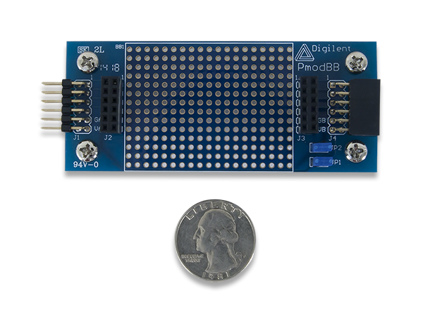
Physical Dimensions
The pins on the pin header are spaced 100 mil apart. The PCB is 3.5 inches long on the sides parallel to the pins on the pin header and 1.5 inches long on the sides perpendicular to the pin header.
Additional Information
The schematics of the Pmod BB are available here.
As a breadboard, there is no example code that can “demonstrate” an appropriate use of a breadboard.
If you have any questions or comments about the Pmod BB, feel free to post them under the appropriate section (“Add-on Boards”) of the Digilent Forum.