Nexys A7 GPIO Demo

Description
This project is a Vivado demo using the Nexys A7's switches, LEDs, RGB LED's, pushbuttons, seven-segment display, PWM audio output, PDM microphone and USB UART bridge, written in VHDL. When programmed onto the board, all sixteen of the switches are tied to their corresponding LEDs. Every time a switch is toggled, the LED directly above it will toggle with it. If the center push button is pressed, all the LEDs will be tied to ground. The two tri-color LEDs are set to gradually change colors at all times.
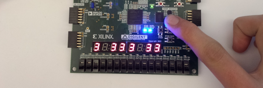
The seven segment display counts up from 0 to 9 as long as no buttons are pressed. As long as BTNU is pressed, the first digit on the seven segment display is turned off. In the same manner, BTNL turns off the second digit, BTNR turns off the third, and BTND turns off the fourth. BTNC turns off the entire display and resets the counter. The microphone which is next to Pmod connector JC, records audio data and sends it to the mono audio output located at J8. To listen to the mics output, you will need to plug in headphones or a speaker.
To use the USB-UART bridge feature of this demo, the Nexys A7 must be connected to a serial terminal on the computer it is connected to over the MicroUSB cable. For more information on how to set up and use a serial terminal, such as Tera Term or PuTTY, refer to this tutorial. Whenever the reset button or BTNC is pressed, the Nexys A7 sends the line “Nexys A7 GPIO/UART DEMO!” to the serial terminal. Whenever one of the D-pad buttons other than BTNC is pressed, the line “Button press detected!” is sent.
Inventory
- Nexys A7 with a MicroUSB Programming Cable
- Vivado installation compatible with the latest release of this demo (2022.1)
- See Installing Vivado, Vitis, and Digilent Board Files for installation instructions.
- Serial Terminal application to receive messages printed by the demo
- See Installing and Using a Terminal Emulator for more information.
- Headphones or Speakers with 3.5mm Audio Jack
Download and Usage Instructions
The following releases of this demo can be used with instructions found in the corresponding READMEs in order to run the demo.
Releases are only compatible with the version of the Xilinx tools specified in the release version number. In addition, releases are only compatible with the specified variant of the board. For example, a release tagged “20/DMA/2020.1” for the Zybo Z7 is only to be used with the -20 variant of the board and Vivado 2020.1.
The latest release version for this demo is highlighted in green.
Note: Releases for FPGA demos from before 2020.1 used a different git structure, and used a different release tag naming scheme.
| Board Variant | Release Tag | Release Downloads | Setup Instructions |
|---|---|---|---|
| Nexys A7-100T | 100T/GPIO/2022.1-1 | Nexys-A7-100T-GPIO-hw.xpr.zip | See Using the Latest Release, below |
| Nexys A7-50T | 50T/GPIO/2022.1-1 | Nexys-A7-50T-GPIO-hw.xpr.zip | See Using the Latest Release, below |
| Nexys A7-100T | 100T/GPIO/2021.1-1 | Nexys-A7-100T-GPIO-hw.xpr.zip | See Using the Latest Release, below |
| Nexys A7-50T | 50T/GPIO/2021.1-1 | Nexys-A7-50T-GPIO-hw.xpr.zip | See Using the Latest Release, below |
| Nexys A7-100T | 100T/GPIO/2020.1-2 | Nexys-A7-100T-GPIO-hw.xpr.zip | See Using the Latest Release, below |
| Nexys A7-50T | 50T/GPIO/2020.1-2 | Nexys-A7-50T-GPIO-hw.xpr.zip | See Using the Latest Release, below |
| Nexys A7-100T | v2018.2-1 | Release ZIP downloads | Github README |
| Nexys A7-50T | v2018.2-1 | Release ZIP downloads | Github README |
Note for Advanced Users: GitHub sources for this demo can be found in the 100T/GPIO/master and 50T/GPIO/master branches of the Nexys-A7 repository. Further documentation on the structure of this repository can be found on this wiki's Digilent FPGA Demo Git Repositories page.
Instructions on the use of the latest release can be found in this dropdown:
- Using the Latest Release
-
Note: This workflow is common across many Digilent FPGA demos. Screenshots may not match the demo you are working with.
Important: These steps are only to be used with releases for Xilinx tools versions 2020.1 and newer. Older releases may require other flows, as noted in the table of releases.
First, download and extract the '*.xpr.zip' file from the demo release, linked above.
- Open a Vivado Project from a Release
-
Launch Vivado
Select the dropdown corresponding to your operating system, below.
- Windows
-
Open Vivado through the start menu or desktop shortcut created during the installation process.

- Linux
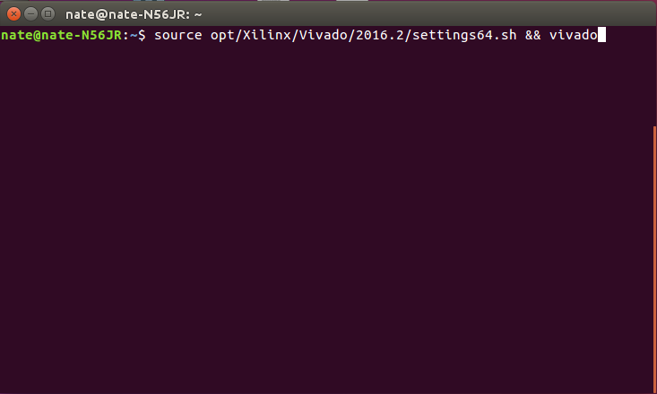
-
Open a terminal, and change directory (cd) to a folder where log files for your Vivado session can be placed, then run the following commands:
source <install_path>/Vivado/<version>/settings64.sh
vivado
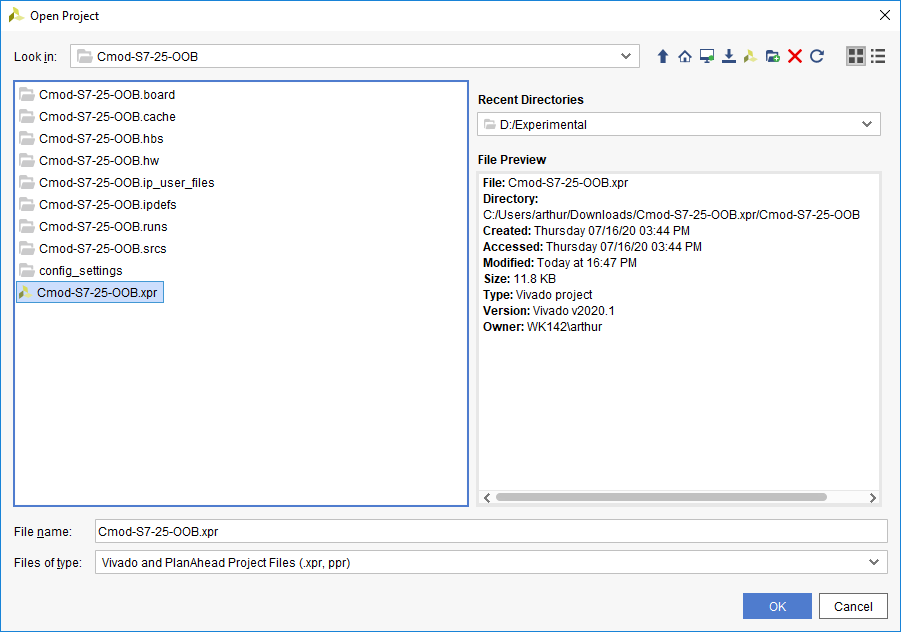
In Vivado's welcome screen, use the Open Project button to navigate to and open the XPR file contained in the folder the release was extracted into.
- Build a Vivado Project
-
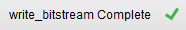
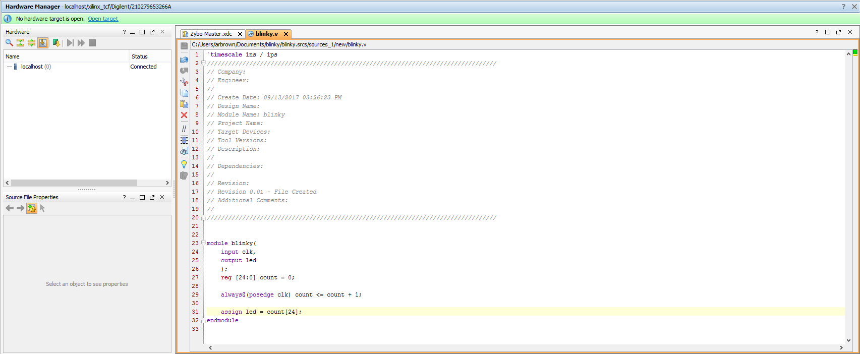
Note that if your project already has a generated bitstream, as indicated by the status in the top right corner of the window reading “write_bitstream Complete!”, then you can skip this section.
Generate a Bitstream
In order to create a file that can be used to program the target board, each stage of the “compilation pipeline” needs to be run.
This starts with Synthesis. Synthesis creates a description of the logic gates and connections between them required to perform the functionality described by the HDL files, given the constraints included in XDC files. To run Synthesis click either
 in the toolbar or
 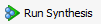 in the Flow Navigator. The output of Synthesis is then passed to Implementation.
Implementation has several steps. The steps that are always run are Opt Design (Optimize the design to fit on the target FPGA), Place Design (Lay out the design in the target FPGA fabric), and Route Design (Route signals through the fabric). To run Implementation click either
 in the toolbar or
 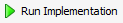 in the Flow Navigator. This output is then passed on to the Bitstream Generator.
The Bitstream Generator generates the final output file needed for programming the FPGA. To run Bitstream Generation click either
 in the toolbar or
 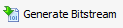 in the Flow Navigator. With no settings changed, the generator will create a '.bit' file.
Depending on the complexity of the design, the board used, and the strength of your computer, the process of building the project can take between 5 and 60 minutes. When complete, a pop-up dialog will appear, prompting you to select one of several options. None are relevant for the purposes of this guide, so click Cancel. The “write_bitstream complete” status message can be seen in the top right corner of the window, indicating that the demo is ready to be deployed to your board.
- Set up the Nexys A7
-
Plug the microUSB programming cable into the Nexys A7's PROG/UART port and the headphones or speaker into the MONO AUDIO OUT port.
- Program a Bitstream onto an FPGA Board
-
Vivado's Hardware Manager can be opened by clicking on Open Hardware Manager at the bottom of the Flow Navigator pane on the left side of the Vivado window.
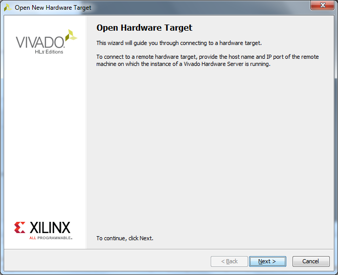
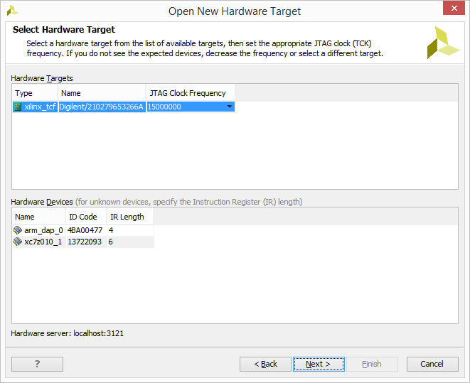
The first step to programming a device is to connect the Vivado Hardware Server to it as a target. To get to the Open Hardware Target wizard click the
 link in the green banner near the top of the window. From the drop-down that opens, select
 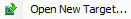 .
.
Once the wizard opens, click Next.
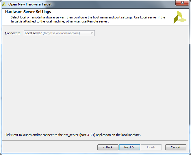
The next screen asks if the hardware server is local or remote. If the board is connected to the host computer choose local, if it is connected to another machine choose remote and fill in the Host Name and Port fields.
Click Next to continue.
This screen gives a list of devices connected to the hardware server. If there is only one connected it will be the only device shown.
Click Next to continue.

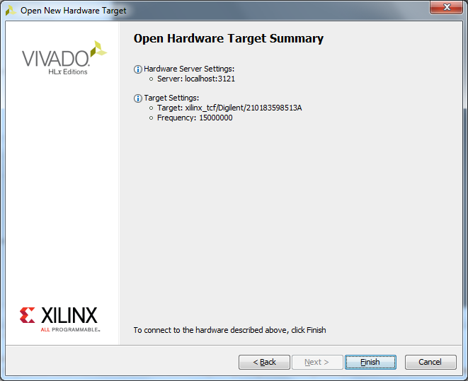
The final screen shows a summary of the options selected in the wizard. Verify the information and click Finish. The board is now connected to the hardware server.

To program the device with the bit file generated earlier, either click the
 link in the green banner at the top of the window or click the
  button in the Flow Navigator under
  . From the drop-down that opens, select the device to program (Example:
  ) and the following window will open:
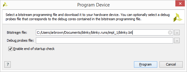
The Bitstream File field should be automatically filled in with the bit file generated earlier. If not, click the
 button at the right end of the field and navigate to
<Project Directory>/<Project Name>.runs/impl_1/ and select the bit file (Example: ). Now click Program. This will connect to the board, clear the current configuration, and program it using the new bit file.
At this point, the demo is now running on your board. Refer to the Description and Functionality sections of this document for more information on what it does.


Functionality
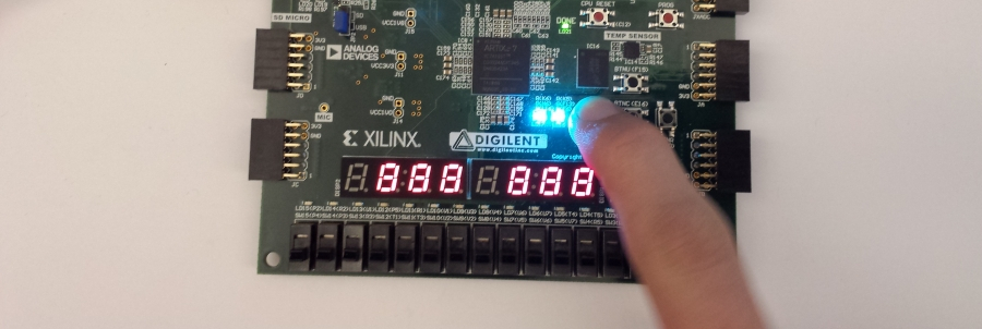
1. Switches and LEDs
For this section, all the switches are tied to their corresponding LED. Every time a switch is toggled, the LED directly above it will toggle with it. If the center push button is pressed, all the LEDs will be tied to ground .
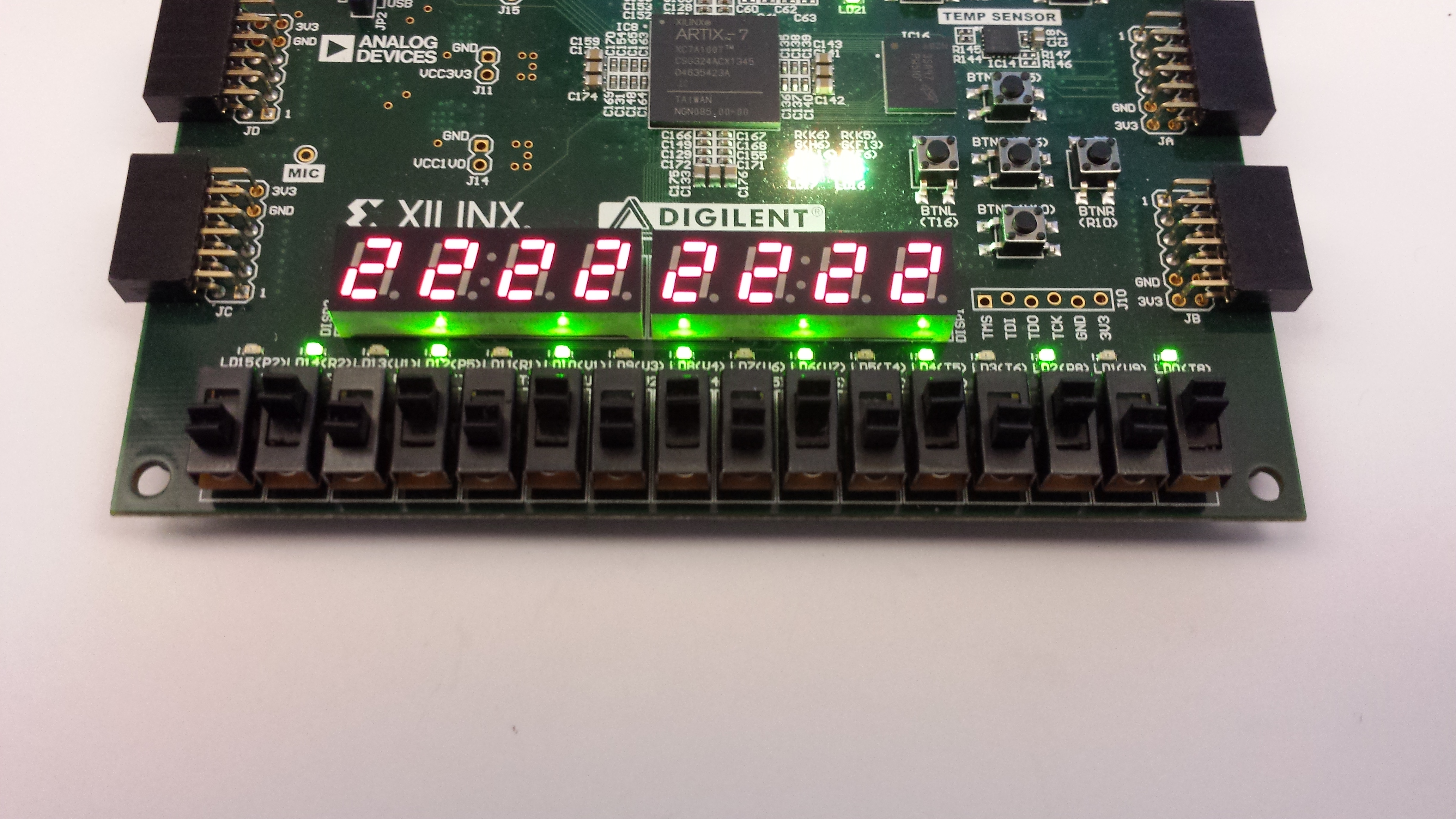


2. Seven Segment Display
The 7-Segment display counts from 0 to 9 on each of its 8 digits. This count is reset when the center button is pressed. Also, single anodes of the 7-Segment display are blanked by holding BTNU, BTNL, BTND, or BTNR. Holding the center button blanks all the 7-Segment anodes.


3. Tri-Color LEDs
The two tri-color LEDs are set to gradually change colors at all times. The user cannot affect them in this demonstration.
4. Microphone to PWM Output
The microphone which is next to Pmod connector JC, records audio data and sends it to the mono audio output located at J8. To listen to the mics output, you will need to plug in headphones or a speaker.
Additional Resources
All materials related to the use of the Nexys A7 can be found on its Resource Center.
For a walkthrough of the process of creating a simple baremetal software project in Vivado and Vitis, see Getting Started with Vivado and Vitis for Baremetal Software Projects. Information on important parts of the GUIs, and indirect discussion of the steps required to modify, rebuild, and run this demo in hardware can also be found here.
For technical support, please visit the FPGA section of the Digilent Forum.