Zynq Pmod ToF Library User Guide
Digilent provides a Pmod ToF Zynq library targeting the Digilent Zybo Z7-20 board, to be used with the Xilinx SDK development environment.
The library accesses the Pmod ToF hardware in order to implement Pmod ToF functionality. It has multiple software modules, corresponding to different hardware modules.
It is designed to run on the Digilent Zybo Z7-20 board, which acts as a system board for the Pmod ToF. The Pmod ToF is attached to the Zybo Z7-20, and is accessed using digital pins over the Pmod connector.
Overview
The main chapters of this user guide are:
Prerequisites
Hardware
- Zybo Z7-20 board
- Pmod ToF
- Micro-USB cable
Software
- Vivado Design Suite & Xilinx SDK 2019.1
- Version 2019.1 must be used to generate the project
- Digilent Board Support Files for Vivado
- Follow the Vivado Board Files for Digilent 7-Series FPGA Boards guide on how to install Board Support Files for Vivado.
- Vivado-Hierarchies
- Follow the Adding a Hierarchical Block to a Vivado IPI Design guide on how to add a Pmod Hierarchical Block.
Downloads
Hardware Configuration
The Vivado hardware configuration (Vivado Block Design) implemented for this demo has the following features:
- Basic Zynq configuration, with UART_PS1 enabled
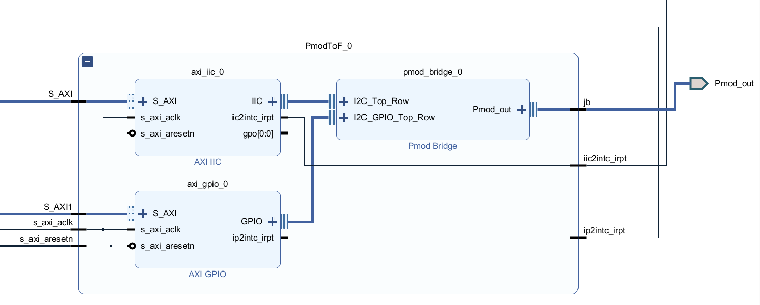
- Pmod ToF Hierarchical Block (found in vivado-hierarchies, See Prerequisites section) which contains the following IPs:
- AXI IIC
- AXI GPIO
- Pmod Bridge
The Pmod ToF must be inserted into Pmod connector JB on Zybo-Z7-20 for this demo. The user can choose to use a different Pmod connector but the pins constrained in the XDC file must be changed for the new Pmod connector.
The user must connect the Pmod ToF's pullup jumpers (JP1, JP2, JP3 and JP4) when using the Pmod ToF Hierarchical Block.
The following image shows the block design.

The following image shows the Pmod ToF Hierarchical Block design (PmodToF_0 expanded).
Library Overall Structure
Description
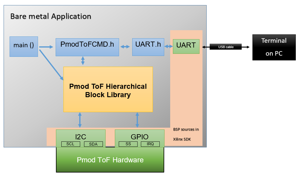
The diagram above shows the general structure of the Pmod ToF library, the library modules, and the relations between them.
The I2C Interface, GPIO Interface and UART Interface belong to the lowest level and are provided by the BSP project in Xilinx SDK. These interfaces implement the communication protocols.
The UART Module provides the communication between the UART interface of the system board (USB - UART interface) and the host computer.
The ISL29501 module, EEPROM Module and PmodToF Module are library modules.
The ISL29501 Module contains the library functions for communication over I2C with the ISL29501 chip.
The EEPROM Module contains the library functions for communication over I2C with the Atmel® AT24C04D EEPROM memory.
The PmodToF Module implements functionality of the Pmod ToF device such as initialization functions, calibration functions, ISL29501 registry and EEPROM memory access functions.
The PmodToFCMD Module is used for interpreting UART commands.
Library Usage
The library can be used as a Whole or as Modules Included in a User Application.
Library Usage as a Whole
The provided software package can be used to access all the Pmod ToF functionality. The main function calls a command interpreter from the PmodToFCMD Module, that provides access to all Pmod ToF functionality.
Library Usage as Modules Included in a User Application
The user may choose to include the PmodToF Module with the ISL29501 Module and the EEPROM Module in specific applications, in order to perform PmodToF calibrations and measurements and can decide not to use the provided command interpreter, the PmodToFCMD Module, implementing a different user interface.
Library Modules
The library modules access the Pmod ToF functionality. These modules are as follows:
PmodToFCMD Module
The PmodToFCMD Module implements a command interpreter that has the following functionality:
- The module listens over UART for individual Pmod ToF commands. The user must provide these commands by using a terminal connected to the USB port corresponding to the connected Zybo Z7-20 board.
- The commands are recognized by the PmodToFCMD Module and are implemented by calls to necessary modules.
- The command interpreter send the command's output messages over UART (see the UART module), which can be seen in the terminal.
It is important to comply with each command's expected formalism. The command interpreter loop is implemented in the PmodToFCMD_CheckForCommand function.
The following list enumerates the commands implemented in the PmodToFCMD module:
For details about calibration and measurement, see the Calibration and Measurement sections.
PmodToFCMD_CheckForCommand
Synopsis:
void PmodToFCMD_CheckForCommand();
Parameters:
<none>
Return Value:
<none>
Description:
This function checks on UART if a command was received.
It compares the received command with the commands defined in the commands array. If recognized, the command is processed accordingly.
Example:
#include “PmodToFCMD.h”
PmodToFCMD_CheckForCommand();
ToFMeasure
Syntax:
“ToFMeasure”
Description:
This command initiates a measurement and displays the distance measured by the device over UART. Before running this command, it is important that a manual calibration was performed or that a calibration was stored in then imported from the EEPROM user area or that factory calibration was restored from EEPROM.
Parameters:
<none>
Response:
After issuing the command: “OK,Distance measured D = x mm.”
ToFStartCalib
Syntax:
“ToFStartCalib,<distance value>”
Parameters:
| <distance value> | This is the real distance value in meters for which the manual calibration is performed. Distance must be more than 5 cm (0.05 m). |
Example:
“ToFStartCalib,1.5”
Calibration is performed at a distance of 1.5 m.
Description:
This command performs a manual calibration. It calls all 3 calibration routines as described in the ISL29501 Firmware Routines (an1724.pdf) documentation.
Response:
| Answer | Meaning |
|---|---|
| “OK,Starting calibration…” | The calibration distance parameter is greater than 5 cm. |
| “ERROR, Incorrect calibration distance(distance is less than 5 cm).” | ERROR, distance value parameter is less than 5 cm. |
| “ERROR, Failed starting manual calibration.” | ERROR, failed to start calibration, EEPROM or ISL29501 device is busy. |
ToFSaveCalib
Syntax:
“ToFSaveCalib”
Parameters:
<none>
Description:
This command is used to write calibration data in the user calibration area of EEPROM.
This command should be issued after changes were made in calibration data(after a manual calibration), in order to save them in the non-volatile memory.
Response:
| Response | Meaning |
|---|---|
| “OK, Calibration stored to EEPROM user space.“ | Success. |
| “ERROR, ToF read over I2C error.” | ERROR, failed to read ISL29501 registers over I2C communication. |
| “ERROR, EPROM write over I2C error.” | ERROR, failed to write EEPROM memory over I2C communication. |
ToFRestoreFactCalib
Syntax:
“ToFRestoreFactCalib”
Parameters:
<none>
Description:
This command it is used to restore the factory calibration data from EEPROM. When this command is run, the factory calibration data from EEPROM is read and then written into the user calibration area of EEPROM and into ISL29501 registers.
Response:
| Response | Meaning |
|---|---|
| “OK,Factory calibration restored.” | Success. |
| “ERROR, Invalid EEPROM magic number.” | ERROR, wrong CRC when reading data from EEPROM. |
| “ERROR, Invalid EEPROM checksum.” | ERROR, wrong Magic Number when reading data from EEPROM. |
| “ERROR, ToF read over I2C error.” | ERROR, failed to read ISL29501 registers over I2C communication. |
| “ERROR, EEPROM write over I2C error.” | ERROR, failed to write EEPROM memory over I2C communication. |
ToFReadSerialNo
Syntax:
“ToFReadSerialNo”
Description:
This command retrieves the 12 digit serial number information from EEPROM and displays the Pmod's serial number over UART.
Parameters:
<none>
Response:
| Response | Meaning |
|---|---|
| “OK,Factory calibration restored.“ | Success. |
| “ERROR, Invalid EEPROM magic number.” | ERROR, wrong CRC when reading data from EEPROM. |
| “ERROR, Invalid EEPROM checksum.” | ERROR, wrong Magic Number when reading data from EEPROM. |
PmodToF Module
The PmodToF library module implements Pmod ToF related functions.
These functions configure and initialize the Pmod ToF device over I2C and access Pmod ToF functionality such as performing calibrations and measurements and, R/W operations from EEPROM and ISL29501 registers.
For more details see the ISL29501 - Time of Flight(ToF) integrated circuit and EEPROM Memory sections.
In order to implement the I2C communication, the PmodToF module accesses functions implemented in ISL29501 Module and EEPROM Module. It uses digital IO pins exposed in the Pmod ToF connector: SCL(I2C clock) and SDA (I2C data). The ISL29501 additionally uses IRQ(Interrupt) and SS(Sample start). While the IRQ and SS pins are specific to ISL29501 chip, the I2C lines (data and clock) are shared with the EEPROM device.
The PmodToF module contains library functions for performing calibration and measurement. Calibration ensures the accuracy of measurement by making adjustments to correct measurement error. For more details about calibration and measurement, see the Calibration and Measurement sections.
The PmodToF Module's functions are accessed by PmodToFCMD Module. See Library Overall Structure for more details about the interaction between modules.
The PmodToF functions can be grouped in the following way:
- Initialization:
- Calibration:
- Measurement:
- R/W operations from EEPROM user area:
- Restoring factory calibration and getting the device serial number from EEPROM
PmodToF_Initialize
Synopsis:
void PmodToF_Initialize();
Parameters:
<none>
Return Value:
<none>
Description:
This function initializes the EEPROM and ISL29501.
It sets the ISL29501 chip address and EEPROM chip address for communication over I2C protocol and initializes
the ISL29501 registers (see the ISL29501 - Time of Flight(ToF) integrated circuit section), as described in the ISL29501 Firmware Routines (an1724.pdf) documentation for ISL29501 Chip Initialization.
Example:
#include “PmodToF.h”
PmodToF_Initialize();
PmodToF_start_calibration
Synopsis:
uint8_t PmodToF_start_calibration(double actual_distance);
Parameters:
| < actual_distance > | This is the correct distance value in meters for which the manual calibration is performed. Distance needs to be more than 5 cm (0.05 m). |
Return Value:
uint8_t - The error code:
| ERRVAL_SUCCESS | 0 | success |
| ERRVAL_INCORRECT_CALIB_DISTACE | 0xED | incorrect calibration distance; it has to be more than 5 cm(0.05 m) |
| ERRVAL_FAILED_STARTING_CALIB | 0xFC | failed to start calibration, EEPROM or ISL29501 device is busy |
Description:
This function performs a manual calibration of device, for the distance that is provided by the value of the actual_distance parameter.
It calls all 3 calibration routines as described in the ISL29501 Firmware Routines (an1724.pdf) documentation.
Example:
#include “PmodToF.h”
ErrCode = PmodToF_start_calibration(distance);
PmodToF_perform_distance_measurement
Synopsis:
double PmodToF_perform_distance_measurement();
Parameters:
<none>
Return Value:
| double distance value | the distance measured by the device |
Description:
This function initiates a measurement and retrieves the measured distance value in meters.
Before calling this function, it is important that a manual calibration was performed or that a calibration was stored in then imported from the EEPROM user area or that factory calibration was restored from EEPROM.
It follows the steps for making a distance measurement, as described in the ISL29501 Firmware Routines (an1724.pdf) documentation.
Example:
#include “PmodToF.h”
measured_distance = PmodToF_perform_distance_measurement();
PmodToF_ReadCalibsFromEPROM_User
Synopsis:
uint8_t PmodToF_ReadCalibsFromEPROM_User();
Parameters:
<none>
Return Value:
uint8_t - The error code:
| ERRVAL_SUCCESS | 0 | success |
| ERRVAL_EPROM_MAGICNO | 0xFD | wrong magic number when reading data from EEPROM |
| ERRVAL_EPROM_CRC | 0xFE | wrong checksum when reading data from EEPROM |
Description:
This function reads the user calibration data from EEPROM.
Example:
#include “PmodToF.h”
uint8_t ErrCode = PmodToF_ReadCalibsFromEPROM_User();
PmodToF_WriteCalibsToEPROM_User
Synopsis:
uint8_t PmodToF_WriteCalibsToEPROM_User();
Parameters:
<none>
Return Value:
uint8_t - The error code:
| ERRVAL_SUCCESS | 0 | success |
| ERRVAL_EPROM_WRITE | 0xFA | failed to write EEPROM over I2C communication |
| ERRVAL_ToF_READ | 0xF6 | failed to read ISL29501 registers over I2C communication |
Description:
This function writes calibration data to the user calibration area of EEPROM.
It must be called after changes are made to calibration data(after a manual calibration),in order to save them in the non-volatile memory.
Example:
#include “PmodToF.h”
uint8_t ErrCode = PmodToF_WriteCalibsToEPROM_User();
PmodToF_RestoreAllCalibsFromEPROM_Factory
Synopsis:
uint8_t PmodToF_RestoreAllCalibsFromEPROM_Factory();
Parameters:
<none>
Return Value:
uint8_t - The error code:
| ERRVAL_SUCCESS | 0 | success |
| ERRVAL_EPROM_MAGICNO | 0xFD | wrong magic number when reading data from EEPROM |
| ERRVAL_EPROM_CRC | 0xFE | wrong checksum when reading data from EEPROM |
| ERRVAL_EPROM_WRITE | 0xFA | failed to write EEPROM over I2C communication |
| ERRVAL_ToF_READ | 0xF6 | failed to read ISL29501 registers over I2C communication |
Description:
This function restores the factory calibration data from EEPROM.
Factory calibration data is read from EEPROM and written into the user calibration area of EEPROM and into the ISL29501 calibration registers.
Example:
#include “PmodToF.h”
uint8_t ErrCode = PmodToF_RestoreAllCalibsFromEPROM_Factory();
PmodToF_ReadSerialNoFromEPROM
Synopsis:
uint8_t PmodToF_ReadSerialNoFromEPROM(char *pSzSerialNo);
| char *pSzSerialNo | pointer to a character string to hold the serial number sequence |
Return Value:
uint8_t - The error code:
| ERRVAL_SUCCESS | 0 | success |
| ERRVAL_EPROM_MAGICNO | 0xFD | wrong magic number when reading data from EEPROM |
| ERRVAL_EPROM_CRC | 0xFE | wrong checksum when reading data from EEPROM |
Description:
This function retrieves the Serial Number information (12 characters) from EEPROM .
It is important that the caller of this function allocates enough space in pSzSerialNo.
Example:
#include “PmodToF.h”
char SerialNo[13];
uint8_t ErrCode = PmodToF_ReadSerialNoFromEPROM(SerialNo);
ISL29501 Module
The ISL29501 Module is used by the PmodToF Module for purposes internal to the library (initialization and R/W operations) to communicate over I2C with the ISL29501 chip.
See the ISL29501 - Time of Flight(ToF) integrated circuit section for more details.
EEPROM Module
The EEPROM Module is used by the PmodToF Module for purposes internal to the library (initialization and R/W operations) to communicate over I2C with the Atmel® AT24C04D memory chip.
See the EEPROM Memory section for more details.
UART Module
The UART Module implements the functionality needed to communicate with the host computer using the UART_PS1 hardware interface of the Zybo Z7 - 20 board, connected to the USB - UART.
For example, using this module, UART communication between the Zybo Z7 - 20 and a PC can be implemented over a USB cable. Connecting the Zybo Z7-20 to the PC creates a new COM port which can be used in a simple terminal application.
The module initializes the UART without interrupts. The polling method is used to receive available characters.
This module has no PmodToF functionality. It is just included to provide communication capabilities. It doesn't have to be include in an application that doesn't need communication (for example an application that uses an LCD connected to the Zybo Z7-20 board).
We recommend initializing the module at a baud rate of 115200 for a basic application.
This module is only accessed by PmodToFCMD Module.
The module provides:
- Initialization function:
- Character string transmit function:
- Character string receive function:
UART_Init
Synopsis:
u8 UART_Init(u32 dwBaudRate);
Parameters:
| u32 dwBaudRate | UART baud rate for example 115200 corresponds to 115200 baud |
Return Value:
uint8_t - The error code:
| ERRVAL_SUCCESS | 0 | success |
| ERRVAL_DMM_UARTERROR | 0xEE | UART Init error |
Description:
This function initializes the UART-PS controller at the specified baud rate.
Example:
#include “uart.h”
UART_Init(115200);
UART_PutString
Synopsis:
void UART_PutString(char szData[])
Parameters:
| char szData[] | the zero terminated string containing characters to be transmitted over UART |
Return Value:
<none>
Description:
This function transmits all the characters from a null-terminated string over UART1.
The terminating null character is not sent.
Example:
#include “uart.h”
UART_PutString(“Hello World\r\n”);
UART_GetString
Synopsis:
uint8_t UART_GetString(char* pchBuff, int cchBuff)
Parameters:
| char* pchBuff | pointer to a char buffer to hold the received zero terminated string |
| int cchBuff | size of the buffer to hold the zero terminated string |
Return Value:
<none>
Description:
This function provides a null-terminated string received over UART1 which was placed in the circular buffer by the UART interrupt handler.
If a received string is available in the circular buffer, the string is copied in the pchBuff string and its length is returned.
Otherwise, the function returns 0.
Example:
#include “uart.h”
cchi = UART_GetString(uartCmd, 0x40);
ISL29501 - Time of Flight(ToF) Integrated Circuit
The ISL29501 chip is accessed using digital IO pins exposed in the Pmod ToF connector: SCL (clock bus), SDA (data bus), IRQ(Interrupt) and SS(Sample start).
SCL and SDA are used by the I2C bus and are shared with the Atmel® AT24C04D memory chip. IRQ and SS are GPIO pins.
The ISL29501 chip can be accessed over the I2C protocol at the address: 0x57h.
Every time the board is power cycled and the Zybo Z7-20 board is programmed, the PmodToF_Initialize function is called and programs values imported from EEPROM user area, into the initialization registers.
The Chip Initialization routine is described in ISL29501 Firmware Routines (an1724.pdf) documentation.
These values (see table below) are set by Digilent and the user must be very careful changing them. In this situation the user must modify these values before performing manual calibration.
Please read ISL29501 documentation before proceeding.
NOTE: Prior to restoring the factory calibration, if the user modified these register values (located in PmodToF_Initialize function), they must be restored to the values specified below, otherwise the measurements won't be correct.
| Register address | Data |
|---|---|
| 0x10 | 0x04 |
| 0x11 | 0x6E |
| 0x13 | 0x71 |
| 0x18 | 0x22 |
| 0x19 | 0x22 |
| 0x60 | 0x01 |
| 0x90 | 0x0F |
| 0x91 | 0xFF |
Calibration
In order to perform an accurate distance measurement, the Pmod ToF needs to be calibrated. The EEPROM stores two sets of calibration values.
The factory calibration set contains the values for the generic calibration, loaded when the device was manufactured and cannot be altered.
The user calibration set contains the calibration values used to correct the measurements. The user can overwrite the user calibration set upon performing their own calibration. Initially the user calibration set is loaded with the factory calibration values. It can always be restored to factory calibration by running the ToFRestoreFactCalib command or by calling the PmodToF_RestoreAllCalibsFromEPROM_Factory function .
At the factory, the EEPROM was programmed with a generic calibration profile that helps in performing measurements in a range of 30cm-3m.
If the user wants more precise measurements, a manual calibration can be done by running the ToFStartCalib command or by calling the PmodToF_start_calibration function.
The calibration procedure involves three types of calibrations required for the Pmod ToF: magnitude calibration, crosstalk calibration and distance calibration.
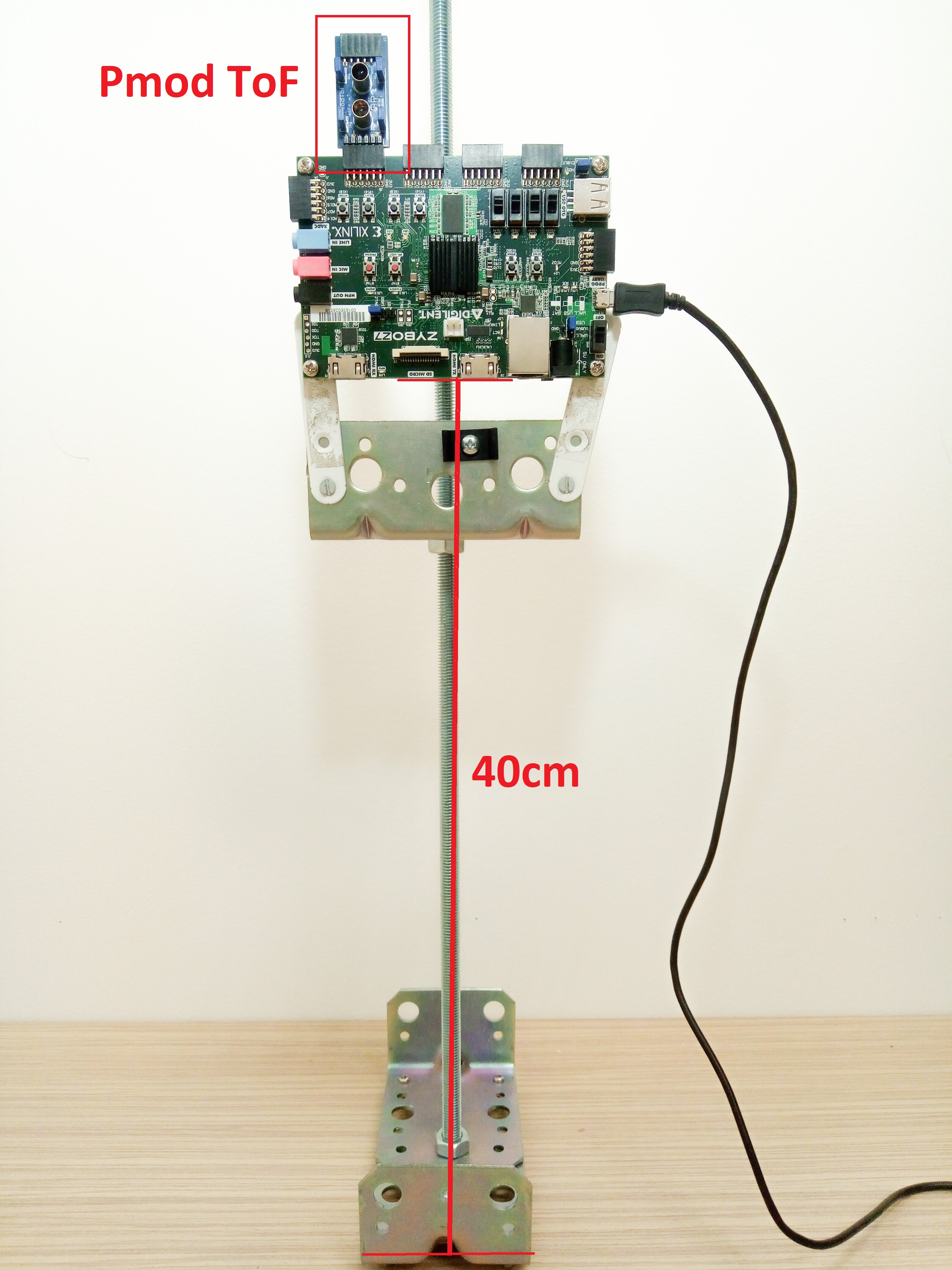
For the calibration procedure, the user needs a support setup that holds the Zybo Z7-20 board vertically and at least 40 cm above the ground or table.
The following image is an example of the setup described.
The steps for the calibration procedure are:
- The Magnitude Calibration does not require any special setup. This is an internal calibration so external conditions are not relevant.
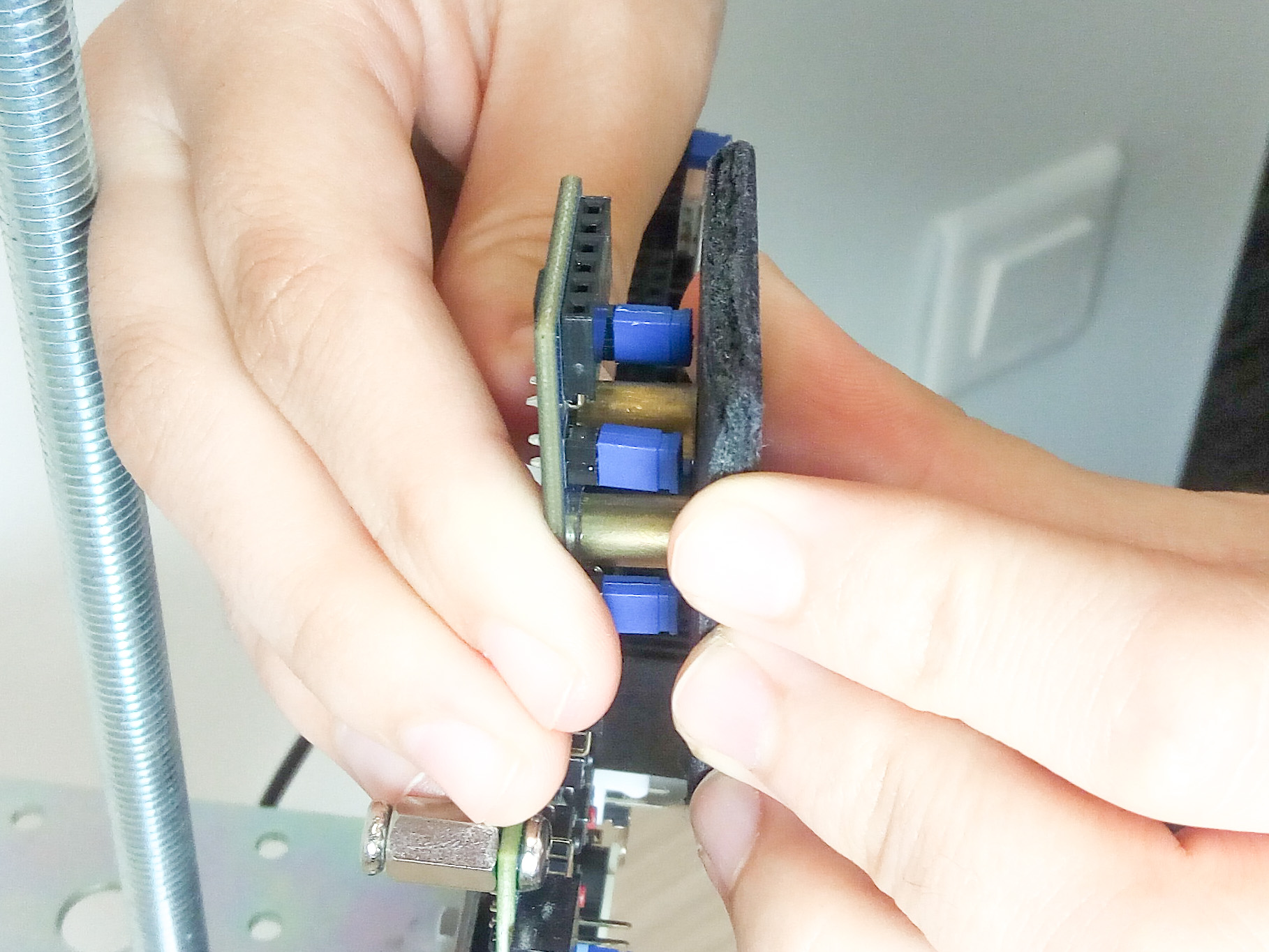
The user needs to wait 5 seconds for this calibration to be performed. - To set up Crosstalk Calibration, the emitter light must be blocked from reaching the photodiode. For this calibration to be accurate, it is critical that all light is blocked. With all light blocked, only the noise signals reach the PD circuits. This can be done by covering both optics with the foam included in the package to make sure there is no return path for the IR signal emitted by the LED (see image below). If the optics are not correctly covered, it will result in large errors when measurements are taken. The crosstalk calibration process is slower than magnitude calibration. The user needs to wait 10 seconds for this calibration to be performed.
- To set up Distance Calibration, the Pmod must be placed at a known distance from a white target (a target with high IR reflective capacity) that completely covers the field of view of Pmod's emitter diode. The board must be positioned so that the emitter light does not reflect off a table top, wall, or other object. A good estimation is to keep all objects at least two times the calibration distance multiplied by the tangent of twice the viewing angle (+/-3°) of the emitter(1). The user can picture an imaginary cylinder, whose radius is calculated as below, with the board and the target at the ends (example: for a calibration distance of 30cm, the cylinder would have a radius of 6.3cm).
$$Radius=2*CalibDist*tan(2*3°)\tag{1}$$
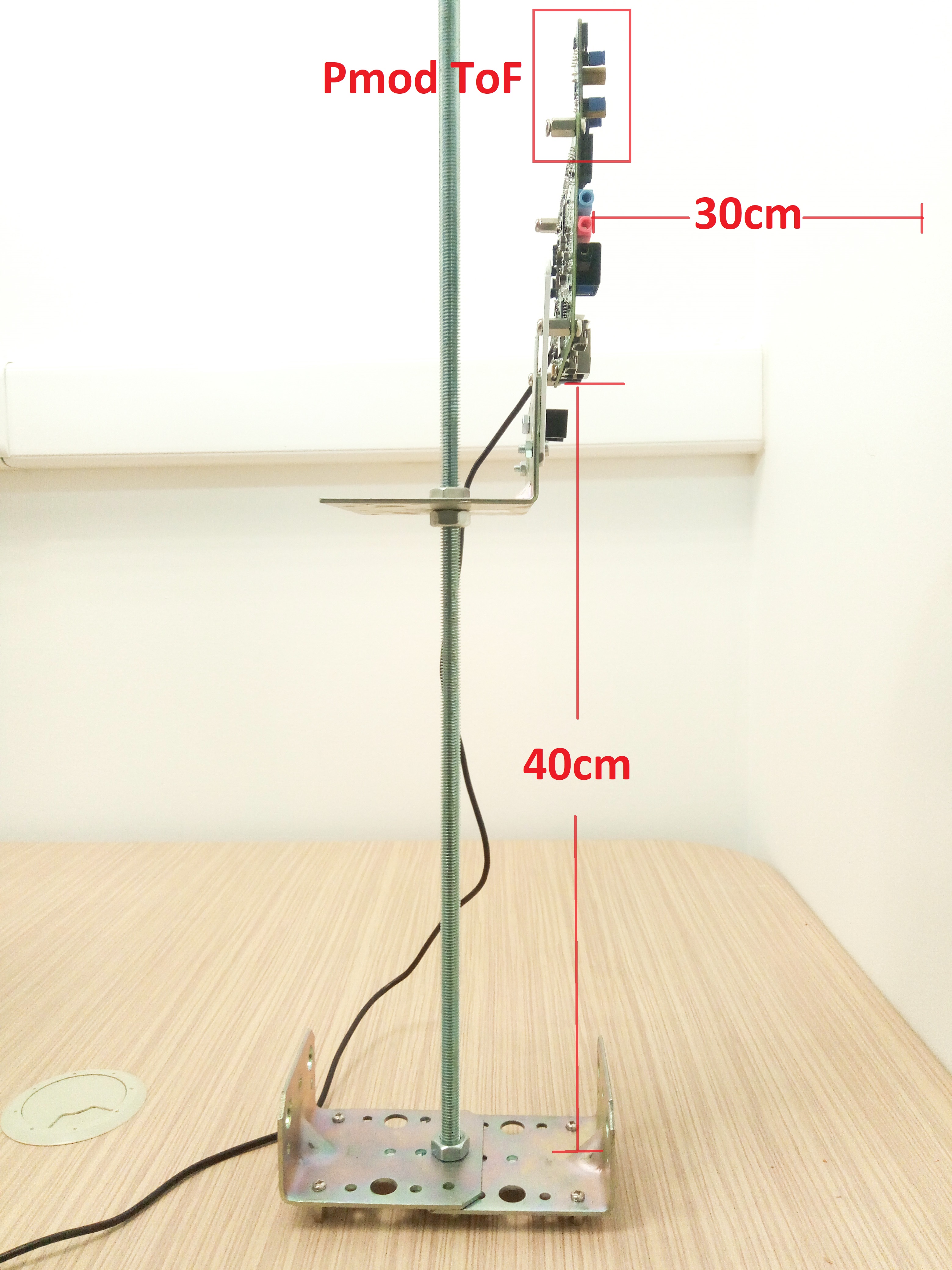
The user should pick a calibration distance between the minimum and maximum expected measurement distance. The Pmod ToF should be also placed at least 40cm above the ground or table. The farther the measurement is taken from the Pmod ToF, the bigger the area should be. The user needs to wait 10 seconds for this calibration to be performed.
The following image is an example setup for a calibration distance of 30cm.
NOTE:Information about the moment when every calibration starts and ends will be displayed in the terminal application over UART.
For more details about the calibration process, see Best Practices for TOF Crosstalk Calibration.
Calibration Registers
Calibration Registers can be found in the ISL29501 documentation, at SECTION 0.4A: CLOSED LOOP CALIBRATION REGISTERS .
Measurement
A measurement can be performed by running the ToFMeasure command or by calling PmodToF_perform_distance_measurement function.
EEPROM Memory
The Pmod ToF provides a non-volatile EEPROM memory Atmel® AT24C04D which has 4-Kbits of available space.
The Atmel® AT24C04D memory chip is accessed using digital IO pins exposed in the Pmod ToF connector: SCL (clock bus) and SDA (data bus).
It shares the I2C bus with the ISL29501 chip.
The Atmel® AT24C04D is internally organized as 32 pages of 16 bytes each.
The EEPROM stores two sets of calibration values. The factory calibration set contains the values for the generic calibration performed when the device was manufactured and cannot be altered.
The user calibration set contains the values generated when the user performs their own calibration. Initially the user calibration set is loaded with the factory calibration vales. It can always be restored running the command ToFRestoreFactCalib or calling the function PmodToF_RestoreAllCalibsFromEPROM_Factory.
| Section Content | Section Base Address | Size |
|---|---|---|
| Serial Number | 0x00 | 16 bytes |
| User calibration data | 0x10 | 16 bytes |
| Factory calibration data | 0x20 | 16 bytes |
| Free Memory | 464 bytes |
Accessing the device requires an 8-bit Device Address word.
The memory can be accessed over the I2C protocol at the address: 0x50h and follows the structure below :
| Device Address | |||||||
|---|---|---|---|---|---|---|---|
| Bit7 | Bit 6 | Bit 5 | Bit 4 | Bit 3 | Bit 2 | Bit 1 | Bit 0 |
| 1 | 0 | 1 | 0 | 0 | 0 | A8 | R/W |
Bit 0 of the Device Address byte is the Read/Write operation select bit. Bit 1 of the Device Address byte is the most significant bit of the 9-bit memory array word address.
| 9-bit memory array word address | ||||||||
|---|---|---|---|---|---|---|---|---|
| Page number | Address in memory page | |||||||
| Bit 8 | Bit7 | Bit 6 | Bit 5 | Bit 4 | Bit 3 | Bit 2 | Bit 1 | Bit 0 |
| A8 | A7 | A6 | A5 | A4 | A3 | A2 | A1 | A0 |
The EEPROM is used to store the following system information:
- Serial number:
- 12 byte payload (see Serial Number)
- 2 extra bytes: magic number, checksum
- 2 dummy bytes used to align to 16 bytes
- Total 16 bytes = one memory page.
- User Calibration:
- 13 byte payload (see Calibration Registers)
- 2 extra bytes: magic number, checksum
- 1 dummy byte used to align to 16 bytes
- Total 16 bytes = one memory page.
- Factory Calibration:
- 13 byte payload (see Calibration Registers)
- 2 extra bytes: magic number, checksum
- 1 dummy byte used to align to 16 bytes
- Total 16 bytes = one memory page.
A total of 3 memory pages (48 bytes) are used, see the address space table from above.
Note that the structure of User Calibration area is identical to the structure of the Factory Calibration area.
For more details about the Calibration process, read more in the Calibration section.
Each of the memory sections mentioned above contains, for safety reasons, additional information:
- a byte containing a specific magic number (0xEB)
- a byte containing the checksum of all the bytes written in the specific section
When reading a section's content from EEPROM, these two security bytes are checked, returning errors when mismatches are found.
Serial Number
Each board has a unique serial number (called SerialNo), built as follows:
- 6 character Pmod ToF prefix (Digilent ID + Schematic ID): “210356”
- 6 character unique serial of each board (read from the barcode label, after ‘D’): for example “A76C0C”
Example of a Pmod ToF SerialNo: “210356A76C0C”
This is written in the EEPROM during the manufacturing procedure and shouldn’t be altered by the user.

