Nexys Video User Demo

Overview
Features Used
| Not Used | Used | |
|---|---|---|
| 8 user switches | X | |
| 8 user LEDs | X | |
| 128×32 monochrome OLED display | X | |
| USB-UART Bridge | X | |
| 160-pin FMC LPC connector | X | |
| Micro SD card connector | X | |
| HDMI Sink and HDMI Source | X | |
| DisplayPort Source | X | |
| Audio codec w/ four 3.5mm jacks | X | |
| 5 user push buttons | X | |
| User EEPROM | X | |
| 10/100/1000 Ethernet PHY | X | |
| 512MiB 800Mt/s DDR3 Memory | X | |
| Serial Flash | X | |
| Four Pmod ports | X | |
| Pmod for XADC signals | X | |
| USB HID Host | X |
Description
The Nexys Video User Demo project demonstrates usage of most of the the Nexys Video's peripheral devices. . The behavior is as follows:
- The 8 User LEDs are tied to the 8 User Switches. Pressing any of the 5 push buttons inverts the LEDs.
- The audio demo records a 5 second sample from microphone (J6) or line in (J7) and plays it back on headphone out (J4) or line out (J5). Record and playback is started by pushbuttons (described in the table below).
- The Ethernet can be plugged into a network and is configured to work as an Echo Server.
- With a DVI source connected to J9 (HDMI IN), the demo works as a pass-through buffer outputting the data on DVI output J8 (HDMI OUT) and also J10 (DISPLAYPORT OUT).
- In the absence of a DVI source, the demo switches the video output to an internally generated pattern.
- A USB mouse can be connected and used to control the pointer from the DVI output.
- The XADC is set up to monitor the internal FPGA temperature, VCCINT voltage and VCCAUX voltage.
- The on-board OLED shows the Digilent logo on power-up. After two seconds, it switches to display the XADC readings and the local IP address.
- The Nexys Video also sends status messages and XADC readings through the UART terminal. It is configured to work at a baud rate of 115200 with 8 data bits, 1 stop bit, and no parity.
Prerequisites
Skills
- Basic familiarity with Vivado
- This experience can be found by walking through our “Getting Started with Vivado” guide
Hardware
- Nexys Video FPGA board
- Micro-USB cable
- Nexys Video Power Supply
- Ethernet cord (for echo server)
Software
- Vivado Design Suite 2015.X
- Newer/older versions can be used, but the procedure may vary slightly
Downloads
Nexys Video User Demo – ZIP
How to...
1. Open the Project
1.1) Download the project linked in the download section and unzip it in the location of your choosing.
1.2) Open NexysVideoGPIODemo.xpr in Vivado.
2. Build the Project
2.1) Click Generate Bitstream on the left hand menu towards the bottom. Vivado will run through both Run Synthesis and Run Implementation before it generates the bitstream automatically.
Note: If you want, you can click each step by itself in the order of Run Synthesis, Run Implementation and then Generate Bitstream.

3. Export to SDK
3.1) Export the microblaze project by going to File>Export>Export Hardware. Click the check box to Include the bitstream, and export it local to project. This will create a .sdk folder in your project directory. Afterwards, click File>Launch SDK to launch Xilinx SDK.
4. Import the SDK files
4.1) In your project Explorer window on the left side, click File>Import then expand the General tab and click Existing Projects into Workspace. Navigate to the download folder, select the sdk folder, and click OK. In the Import window, click Finish to import the SDK project.
5. Program the FPGA
5.1) Click Xilinx Tools>Program FPGA and click Program. Xilinx SDK will then program the FPGA with a microblaze bit file.
6. Program the Microblaze Processor
6.1) Right click on the demo folder and click Run as>Launch on Hardware(GDB). The microblaze program will be programmed onto your Nexys Video.
7. Run the Project
This portion will help you run the demo and observe all its features. Note: In its current state, the CPU_RESET button does not function as it should. To reset the demo, reprogram your Nexys Video using Xilinx SDK.
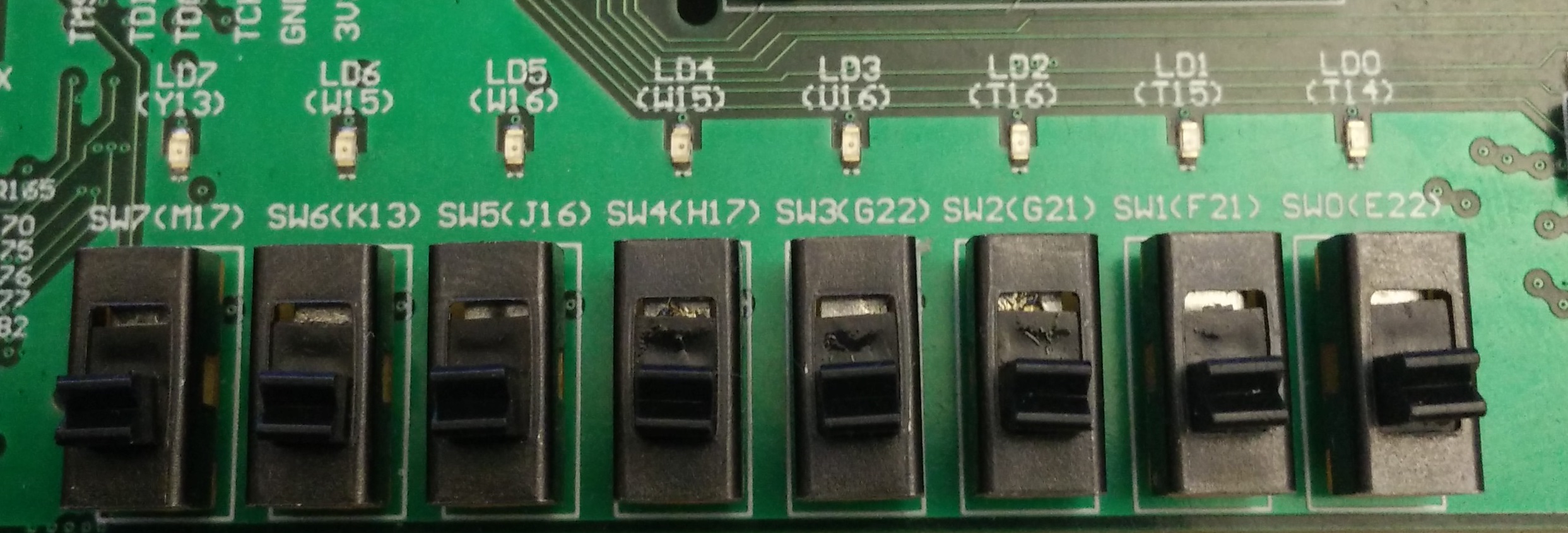
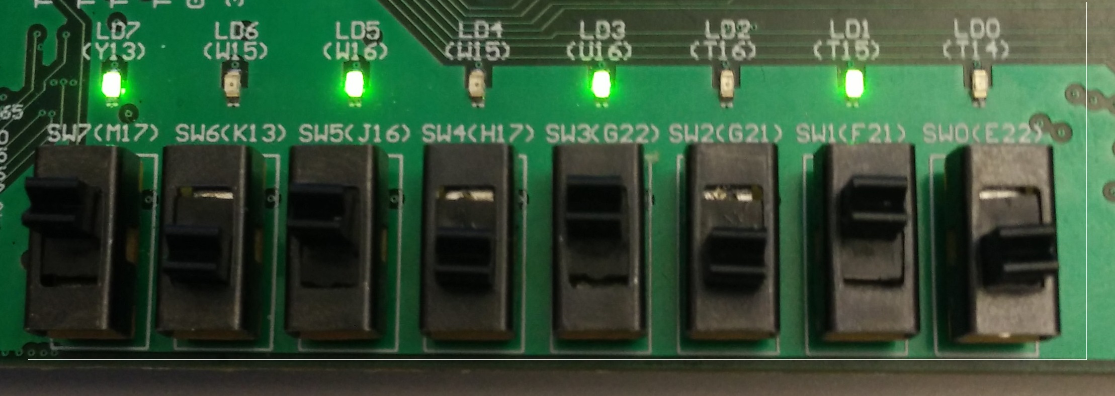
7.1) Using the Switches with Leds
For this section, all the switches are tied to their corresponding led. Every time a switch is toggled, the led directly above it will toggle with it.


7.2) Setting up UART communications
To see the UART communication channel, open a terminal program on your computer set to 112500 baud rate, 8 data bits, no parity bit and 1 stop bit. On startup, the Nexys Video will transmit “Initializing Demo: DONE”, and will start displaying information periodically. This information is the FPGA temperature, VCCINT voltage, VCCAUX voltage, Ethernet status, and the video demo status.

7.3) OLED Display
The OLED display will show information similar to the UART, minus the video demo status.
7.4) HDMI video
Plugging an HDMI cord from HDMI OUT or DISPLAYPORT OUT to a monitor will show a generated video pattern shown below. If an HDMI input is plugged into HDMI IN, the video data will be passed through to the HDMI OUT and DISPLAYPORT OUT ports. A mouse can be plugged into

7.5) Ethernet Echo Server
Plugging the Nexys Video into a router via an Ethernet cable to start up an echo server on a DHCP given IP address on the router. This can be accessed using a terminal program to connect to the IP address given by the DHCP server on port 7.
7.5.1) Setting up a static IP
In the Project Explorer, expand the bist_bsp folder, then open the system.mss file. In the main window, click Modify this BSP's Settings. Follow the picture below to find the lwip_dhcp setting. Set this to false to disable DHCP on the device.
To set the static IP address: In the Project Explorer, navigate to demo>src>eth>eth.c. In this file, find the snippet of code that reads
This is where you can set the static IP of the echo server that will be hosted on your Nexys Video.
#if LWIP_DHCP==1
		ipaddr.addr = 0;
		gw.addr = 0;
		netmask.addr = 0;
	#else
		/* initliaze IP addresses to be used */
		IP4_ADDR(&ipaddr,  192, 168, 1, 100);
		IP4_ADDR(&netmask, 255, 255, 255,  0);
		IP4_ADDR(&gw,      192, 168,   0,  1);

7.6) Audio Demo7.6.1) Recording from an input
To record from the microphone input, press btnu. To record from the line input, press btnr. Once the recording is activated, the message “Start Recording…” will be sent over UART and the demo will record 5 seconds of audio. If any buttons are pressed during the recording, the message “Still Recording…” will be sent over UART.
7.6.2) Playing to an output
To play to the microphone input, press btnd. To play to the line output, press btnl. Once the playback is activated, the message “Start Playback…” will be sent over UART and the demo will play 5 seconds of audio. If any buttons are pressed during the playback, the message “Still Playing…” will be sent over UART.