This is an old revision of the document!
Using the Pattern Generator

Introduction
This guide explains the use of the Patterns instrument in WaveForms. This instrument is used to generate output sequences on a Digilent Test & Measurement Device's digital input/output channels.
Prerequisites
- A Digilent Test & Measurement Device with Digital Input/Output Channels
- A Computer with WaveForms Software Installed
Guide
1. Opening the Pattern Generator
1.1
Plug in the Test & Measurement Device, then start WaveForms and make sure the device is connected.
If no device is connected to the host computer when WaveForms launches, the Device Manager will be launched. Make sure that the device is plugged in and turned on, at which point it will appear in the Device Manager's device list (1). Click on the device in the list to select it, then click the Select button (2) to close the Device Manager.
Note: “DEMO” devices are also listed, which allow the user to use WaveForms and create projects without a physical device.
Note: The Device Manager can be opened by clicking on the “Connected Device” button in the bottom right corner of the screen (3), or by selecting “Device Manager” from the “Settings” menu at the top of the screen.

1.2
Once the Welcome page loads, in the instrument panel at the left side of the window, click on the Patterns button to open the Pattern Generator instrument.

1.3
Once the Pattern Generator instrument opens, the window contains the output plot (1), the configuration panel (2) to left of the plot, and the control toolbar (3) at the top of the window.

2. Using the Pattern Generator
This section walks through setting up the Pattern Generator to generate a signal on a single channel.
2.1 Software Setup
On the left panel, select the “Click to Add channels” button (1 in image at right) or the green plus button ( ). The menu that pops up allows signals to be added as individual lines, a bus, a standard protocol, or a custom protocol. To add individual lines, select “Signal” (2) and use CTRL and/or SHIFT to select multiple lines. For now, select DIO 0 and click “Ok”. Under the Type column, choose “Clock” from the drop-down menu and leave the other settings in their default state.
Return to WaveForms' Welcome page by clicking on its tab at the top left of the screen and select Logic. Alternatively, press the green plus button next to “Welcome” in the tab to add the instrument (3). On the left panel, select the “Click to Add channels” button or the green plus button (). From “Signals” select DIO 0 and click “Ok”. For a detailed tutorial about the Logic Analyzer instrument see Using the Logic Analyzer (REDIRECT).

2.2 Generate Data
In the Pattern Generator instrument, click the Run button ( ) button in the control bar, and then click the Run button in the Logic Analyzer instrument (1 & 2, respectively, in the image to the right). The signal being generated by the Patterns instruments will appear in the Logic Analyzer instrument.

3. Pattern Generator User Interface Overview
This section walks through the wide variety of controls and features available in the Pattern Generator instrument
3.1 Control Interface
The bar near the top contains several options for controlling the pattern generator.
The Run/Stop button starts and stops the pattern generator.
The Trigger drop-down allows for selection of trigger sources from other instruments.
The Wait drop-down allows for configuration of a delay after pressing Run (or the trigger event occurs). The value can be selected from the menu or typed in. If typing, be sure to enter a unit (ns, us, s, ms, ks, Ms) to avoid defaulting to the wrong order of magnitude.
The Run drop-down determines the period of time the pattern generator will generate a pattern for. It also automatically changes the horizontal time axis in the plot (unless manually overridden as shown in section 3.2), making it so the Pattern Generator plot always shows a single period of the pattern (if continuous is selected) or the the entire pattern that will be generated (if a time period is selected).
The Repeat drop-down is available if the Pattern Generator is set to run for a finite amount of time, and will cause the instrument to generate the pattern the set number of times. In “continuous” mode this option is greyed out and set to “infinite”.

3.2 Pattern Signal Controls
Starting from the top left, the plus () and minus ( ) buttons can be used to add or remove channels.
The Show icon ( ) selects which option columns are shown for each channel. The first four columns (Output, Idle, Type, and Parameter1) are available for every type of signal, while the last 2 columns are type-dependent.
The selections available in Parameter1 through Parameter3 menus will change depending on the selection in the Type.
Output switches between four output behaviors:
- PP (Push-Pull): possible output values are 0 and 1.
- OD (Open Drain): possible output values are 0 and Z. Bus values are computed by treating Z as 1. Requires a pull-up resistor
- OS (Open Source): possible output values are Z and 1. Bus values are computed by treating Z as 0. Requires a pull-down resistor
- TS (Tri-State): possible output values are 0, 1, and Z. Bus values containing Z will be displayed as a question mark.
Idle determines if the line is set the initial value, 0, 1, or Z when no signal is being driven through
Type determines the output types. Since the Parameter columns depend on Type, they will be described alongside the signal type:
(NOTE: Not all parameters are used for all signal types.)
- Constant: holds the signal as a constant, set by Parameter 1. Allowable states are determined by the Output column described above.
- Clock: generates a clock signal. The frequency is set by Parameter1, the duty cycle percentage is set by Parameter2, and the phase in degrees is set by Parameter3
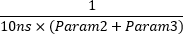
- Pulse: generates a pulse signal. Parameter1 determines if the signal is active high or low, the number of data points to hold the signal low is set by Parameter2, and number of data points to hold the signal high is set by Parameter3. By default data point lasts 10ns, so use the following formula to determine the pulse frequency:
- Random: generates a random pattern of outputs at a frequency determined by Parameter1.
- Custom: generates a custom pattern with frequency determined by Parameter1. The contents of the custom signal can be loaded from a file or set by hand by clicking the Parameter Editor button (see below)
Each signal can be further modified by clicking the Parameter Editor button ( ), located to the left of the Output column. Each Type selection will generate a different menu type.
Use the Properties button ( ) to change the name or DIO pin of each signal line. It is located to the right of the signal name.

3.3 Plot Controls
If the plot needs to be set to show a specific point in the pattern, this can be achieved using the drop-down menus directly below the control bar. The drop-down with the word “Auto” in it needs to be set to “Manual” to change the other two menus.
The Show drop-down will determine how much time per division to display.
The From drop-down will determine what the start point will be on the plot.

Next Steps
For more guides on how to use the Digilent Test & Measurement Device, return to the device's Resource Center, linked from Instrumentation page of this wiki.
For more information on WaveForms visit the WaveForms Reference Manual.
For technical support, please visit the Scopes and Instruments section of the Digilent Forums.