Diodes and LEDs
Diodes
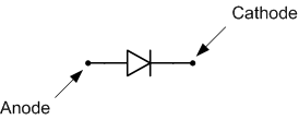
Diodes are two-terminal semiconductor devices that conduct current in only one direction. The terminals of a diode are called the anode and the cathode; a schematic symbol for a diode is shown in Fig. 1. Diodes are intended to conduct current from the anode to the cathode. Diodes have a minimum threshold voltage (or Vth , usually around 0.7V) that must be present between the anode and cathode in order for current to flow. If the anode voltage is not at least Vth greater than the cathode voltage, no current will flow through the diode, as shown in Fig. 2.
As an aside, if the cathode voltage is greater than the anode voltage, the diode is said to be reverse-biased and no current will flow1). If the diode voltage equals the threshold voltage (plus a small amount) in an ideal diode, then unlimited current can flow without causing the voltage across the diode to increase. The ability of a diode to conduct current in only one direction is used in a number of common circuits. Voltage rectifiers, for example, can convert a sinusoidal signal (with both positive and negative components) to a voltage which is purely positive.
LEDs
Light emitting diodes, or LEDs, are a specific type of diode which emits light when current passes through them. The small LED chips are secured inside a plastic housing and emit light at a given frequency when a small electric current (typically 10mA to 25mA) flows through them. When the voltage difference across the LED exceeds the threshold voltage of the LED, current flows through the LED and light is emitted. If the LED voltage is less than the threshold voltage, no current flows and no light is emitted. LEDs are available in a number of colors; the Digilent analog parts kit contains red, yellow, and green LEDs.
Since LEDs are polarized devices, they must be placed in the circuit with the correct orientation; the anode must be at a higher voltage potential than the cathode in order for the diode to emit light. An LED schematic symbol is shown in Fig. 3 below with a sketch of a physical LED. The anode and cathode on a physical LED can be distinguished by identifying some specific characteristics; the anode pin is longer than the cathode pin and the cathode side of the plastic diffusion lens is typically slightly flattened.
Important Points
- Diodes are usually intended to flow current in only one direction—from the anode to the cathode.
- In order to flow current, the anode voltage must be higher than the cathode voltage by at least the diode threshold voltage. If the voltage difference between the anode and the cathode is lower than the threshold voltage, no current passes through the diode.
- The previous point, like any good rule, has exceptions. We will address these later as appropriate.
- Light emitting diodes (LEDs) produce light when current passes through them.
- For an LED, the anode and cathode can be identified by the length of the leads on the diode—the anode lead is longer than cathode lead. In addition, the base of the lens of the LED is slightly flattened on the cathode side.
Test Your Knowledge
- Several voltage differences are indicated across the LEDs below. Indicate whether the voltages will result in current flow.
Answers
- Nonzero, current is from a to b.
- Zero (applied voltage is less than threshold voltage).
- Nonzero, current is from a to b.
- Zero (the value of the voltage is greater than the threshold voltage, but the cathode voltage is higher than the anode voltage.)


