Voltage Divider
Voltage dividers are commonly used circuits that split an applied overall voltage into a smaller desired voltage level.
Figure 1 shows a simple voltage divider using fixed resistors to illustrate its functionality. For this illustration, we assume that the resistors are connected in series, and all current flowing out of the 5V voltage source, flows directly through R1 into R2, and then back to the voltage source (no current detours out the Vout wire).
In the “Button Controlled LEDs” project we briefly mentioned Kirchhoff's voltage law (KVL), which states that the sum of voltage drops (the difference in potential energy across a component) in a circuit loop must equal zero. We will use this property to determine the voltage drops across the individual components in our example circuit.
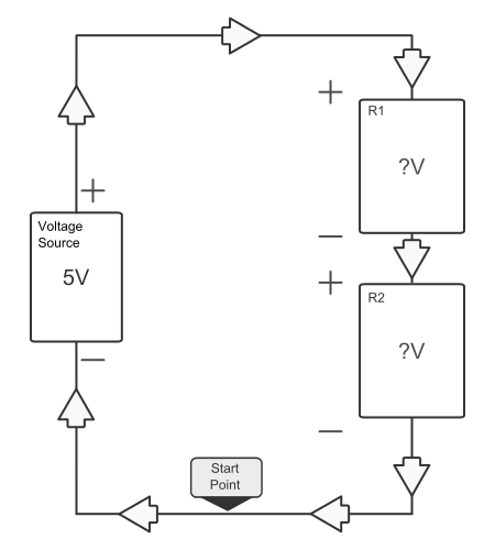
Figure 2 shows a simplified block diagram of the same voltage divider circuit. Going in a clockwise loop around the circuit, we can write down the voltage drop of each component as a term in a governing equation. The sign of the term is determined by the terminal. For example, going clockwise from the start point, the first component reached is the voltage source. The sign of the term is negative since we entered the negative terminal of the voltage source. (There is a link to Kirchhoff's voltage law as well as active/passive sign convention if this seems unfamiliar).
So overall, the governing equation is:
$$\large -5V + V_{R1} + V_{R2} = 0V$$
The voltage drop across $R_{1}$ and $R_{2}$ are unknown, so we designate them as $V_{R1}$ and $V_{R2}$ accordingly. This leaves us an equation with two unknown variables.
Using Ohm's law, $(V = IR)$, we can simplify and reduce the equation to just one unknown variable.
$$\large-5V + R_{1}I + R_{2}I = 0V$$
(Remember the resistors are in series, so the current that flows through $R_{1}$ is the same as $R_{2}$).
Rearranging the equation:
$$I = \large5V * \frac{1}{R_{1} + R_{2}}$$
This tells us the exact value of the current flowing through each resistor. With this value we can find an individual voltage drop by simply multiplying the current value times the components resistance value (another application of Ohm's law).
Therefore:
$$\large V_{R2} = I * R2 = 5V * \frac{R2}{R1 + R2}$$
$$\large V_{R1} = I * R1 = 5V * \frac{R1}{R1 + R2}$$
Referring back to Fig. 2, VOUT is the voltage drop across $R_{2}$ (with resistance values as follows.)
$$R_{2} = 2k\Omega$$ $$R_{1} = 1k\Omega$$ $$\large\frac{2k\Omega}{1k\Omega + 2k\Omega}* 5V = Vout = 3.3V$$
In general, a closed form equation can be used to determine the output of a voltage dividers.
$$\large V_{out} = V_{source} \frac{R_{out}}{ R_{1} + R_{2} … R_{n}}$$
Where $R_{1} + R_{2} … R_{n}$ is any number of resistors connected in series (there can be more than just two), and $R_{out}$ is the resistor whose voltage drop you are measuring as the output of the circuit. (It is also important to note that this equation is only valid for resistors connected in series).


