Kirchhoff's Voltage Law
Understanding Loops in a Circuit
Kirchhoff's current law and Kirchhoff's voltage law are the basis for analysis of lumped parameter circuits. These laws, together with the voltage-current characteristics of the circuit elements in the system, provide us with the ability to perform a systematic analysis of any electrical network. This section presents Kirchhoff's voltage law.
KVL depends upon the concept of a loop. A loop is any closed path through the circuit which encounters no node more than once. Essentially, to create a loop, start at any node in the circuit and trace a path through the circuit until you get back to your original node. The concept of a loop is probably most readily explained through a few simple examples—which we've provided below.
Example 1:

- Kirchhoff's voltage law (commonly abbreviated as KVL) states:
- The algebraic sum of all voltage differences around any closed loop is zero.
- An alternate statement of this law is:
- The sum of the voltage rises around a closed loop must equal the sum of the voltage drops around the loop.
- Or even:
- When going around a loop, you have to get back to the same voltage you started with.
Note
Voltage polarities in the loop are based on assumed polarities of the voltage differences in the loop. As long as the assumed directions of the voltages are consistent from loop to loop, the final result of the analysis will reflect the actual voltage polarities in the circuit.
Example 2:
In the figure below, the assumed polarities of the voltages V1, V2, V3, V4, V5, and V6 are as shown. There are three possible loops in the circuit: a-b-e-d-a , a-b-c-e-d-a , and b-c-e-b. We will apply KVL to each of these loops.
Our sign convention for applying signs to the voltage polarities in our KVL equations will be as follows: when traversing the loop, if the positive terminal of a voltage difference is encountered before the negative terminal, the voltage difference will be interpreted as positive in the KVL equation. If the negative terminal is encountered first, the voltage difference will be interpreted as negative in the KVL equation. We use this sign convention for convenience; it is not required for proper application of KVL, as long as the signs on the voltage differences are treated consistently.
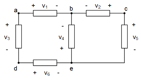
Applying KVL to the loop a-b-e-d-a , and using our sign convention as above results in:
$${V_1} - {V_4} - {V_6} - {V_3} = 0$$
The starting point of the loop and the direction that we loop in is arbitrary; we could equivalently write the same loop equation as loop d-e-b-a-d , in which case our equation would become:
$${V_6} + {V_4} - {V_1} + {V_3} = 0$$
This equation is identical to the previous equation, the only difference is that the signs of all variables have changed and the variables appear in a different order in the equation. We now apply KVL to the loop b-c-e-b, which results in:
$$- {V_2} + {V_5} + {V_4} = 0$$
Finally, application of KVL to the loop a-b-c-e-d-a provides:
$${V_1} - {V_2} + {V_5} - {V_6} - {V_3} = 0$$
Important Point
Kirchhoff's voltage law states that the sum of the voltage differences around any closed loop in a circuit must be zero. A loop in a circuit is any path which ends at the same point at which it starts.
Test Your Knowledge
1. What is the voltage V in the circuit below?

2. What is the voltage V in the circuit below?

3. What is the voltage V in the circuit below? (Hint: this is a trick question.)

4. What are the voltages V1, V2, and V3 in the circuit below?

Answers
1. Looping clockwise, starting from the lower-left corner, results in:
$$- 3V - V + 7V = 0$$
So V = 4V. (Notice when looping, we are taking a voltage difference as positive if we encounter the “+” terminal first, and negative if we encounter the “-” terminal first.
2. Looping clockwise, starting from the lower-left corner, results in:
$$+ 9V - 2V + V = 0$$
So V = -7V. (Notice when looping, we are taking a voltage difference as positive if we encounter the “+” terminal first, and negative if we encounter the “-” terminal first.
3. There is no value of voltage that satisfies this circuit. If you apply KVL around the leftmost loop, you get $3V + 1V - V = 0$, so $V = 4V$. KVL around the rightmost loop results in $V + 7V = 0$, so $V = - 7V$. The two loops give inconsistent results!
The root of the problem is that the given voltages are inconsistent with Kirchhoff's voltage law. If we apply KVL around the outermost loop, we get:
$$3V + 1V + 7V = 0$$
Which is strictly untrue.
4. This answer is detailed through several different situations in the circuit:
- Finding V1: KVL around the loop shown below gives: ${V_1} + 1V + 7V - 3V = 0$, so ${V_1} = - 5V$

- Finding V2: KVL around the loop shown below gives: ${V_2} + 7V = 0$, so ${V_2} = - 7V$

- Finding V3: KVL around the loop shown below gives: ${V_3} - V3 = 0$, so ${V_3} = 3V$

Important Point
You can check your results by applying KVL around other loops in the circuit. For example, the loop to the left below gives: $3V{\rm{ + }}{V_2} + 7V - {V_3} = 0$. Substituting the values for V2 and V3 we determined above gives $3V + \left( { - 7V} \right) + 7V - {\rm{3}}V = 0$, which is true!
Likewise, the loop to the left below gives ${V_1} + 1V - {V_2} - 3V = 0$. Substituting the values for V1 and V2 we determined above gives $\left( { - 5V} \right) + {V_1} - \left( { - 7V} \right) - 3V = 0$, which is also true!
For some more practice, try looping around the entire outer loop as yet another check.
