Real Analog: Chapter 4
- Chapter 4 Materials
-
- Lecture Material:
- Lecture 10 PowerPoint Slides: Linear systems and superposition, Thévenin and Norton's Theorems
- Lecture 11 PowerPoint Slides: Thévenin and Norton's Theorems & examples, source transformations, maximum power transfer
- Lecture 12 PowerPoint Slides: Derivation of maximum power transfer, Thévenin theorem examples, operational amplifiers
- Chapter 4 Videos:
- Lab 4 Video 1: Superposition: Validation of superposition in cases of (a) multiple discrete sources, and (b) single sources with multiple components.
- Lab 4 Video 2: Two-Terminal Networks : Measuring voltage-current characteristics of two-terminal networks. Measurement techniques used are introduced in Resistors I and Resistors II videos.
- Lab 4 Video 3: Thevenin's theorem: Experimental validation of Thevenin's theorem. Measurement techniques used are introduced in Resistors I and Resistors II videos.
-
-
- Exercise Solutions: Chapter 4 exercise solutions
- Homework: Chapter 4 homework problems
4. Introduction and Chapter Objectives
In previous chapters, a number of approaches have been presented for analyzing electrical circuits. In these analysis approaches, we have been provided with a circuit consisting of a number of elements (resistors, power supplies, etc.) and determined some circuit variable of interest (a voltage or current, for example). In the process of determining this variable, we have written equations which allow us to determine any and all variables in the system. For a complex circuit, with many elements, this approach can result in a very large number of equations and a correspondingly large amount of effort expended in the solution of these equations. Unfortunately, much of the physical insight about the overall operation of the circuit may be lost in the detailed description of all of the individual circuit elements. This limitation becomes particularly serious when we attempt to design a circuit to perform some task.
In this chapter, we introduce the concept of a systems level approach to circuit analysis. In this type of approach, we represent the circuit as a system with some inputs and outputs. We then characterize the system by the mathematical relationship between the system inputs and the system outputs. This relationship is called the input-output relation for the system. This representation of a system leads to several network theorems whose use can simplify the analysis of these systems. The network theorems essentially allow us to model a portion of a complicated circuit as a much simpler (but equivalent) circuit. This simplified model can then be used to facilitate the design or analysis of the remainder of the circuit.
The above approach for representing circuits is particularly useful in circuit design; successful design approaches for large circuits typically use a top-down strategy. In this design approach, the overall system is broken down into a number of interconnected subsystems, each of which performs some specific task. This input-output relationships for these individual subsystems can be determined based on the task performed. The subsystems can then be designed to implement the desired input-output relation. An audio compact disc player, for example, will include subsystems to perform filtering, digital-to-analog conversion, and amplification processes. It is significantly easier to designate the subsystems based on their individual requirements than to attempt to design the entire system all at once. We will thus begin to think of the circuits we analyze as systems which perform some overall task, rather than as a collection of individual circuit elements.
After Completing this Chapter, You Should be Able to:
- Define signals and systems
- Represent systems in block diagram form
- Identify system inputs and outputs
- Write input-output equations for systems
- State the defining properties of linear systems
- Determine whether a system is linear
- State conditions under which superposition can be applied to circuit analysis
- Analyze electrical circuits using the principle of superposition
- Define the i-v characteristic for a circuit
- Represent a resistive circuit in terms of its i-v characteristic
- Represent a resistive circuit as a two-terminal network
- Determine Thévenin and Norton equivalent circuits for circuits containing power sources and resistors
- Relate Thévenin and Norton equivalent circuits to i-v characteristics of two-terminal networks
- Determine a load resistance which will maximize the power transfer from a circuit
4.1 Signals and Systems
In this section, we introduce basic concepts relative to systems-level descriptions of general physical systems. Later sections will address application of these concepts specifically to electrical circuits.
A system is commonly represented as shown in the block diagram of Fig. 4.1. The system has some input, u(t), and some output, y(t). In general, both the input and output can be functions of time; the case of constant values is a special case of a time-varying function. The output will be represented as some arbitrary function of the input:
$$y \left( t \right) = f \{ u \left( t \right) \} \qquad (Eq. 4.1)$$
Equation (4.1) is said to be the input-output equation governing the system. The above relationship has only one input and one output - the system is said to be a single-input-single-output (SISO) system. Systems can have multiple inputs and multiple outputs, in these cases there will be an input-output equation for each system output and each of these equations may be a function of several inputs. We will concern ourselves only with SISO systems for now.
Once important aspect of the systems-level approach represented by equation (4.1) and Fig. (4.1) is that we are representing our system as a “black box”. We really have no idea what the system itself is, beyond a mathematical dependence of the output variable on the input variable. The physical system itself could be mechanical, thermal, electrical, or fluidic. In fact, it is fairly common to represent a mechanical system as an “equivalent” electrical system (or vice-versa), if doing so increases the physical insight into the system's operation.
The circuits we analyze can now be thought of as systems which perform some overall task, rather than as collections of individual circuit elements. We will also think of the inputs and outputs of the system as signals, rather than specific circuit parameters such as voltages or currents. This approach is somewhat more abstract than we are perhaps used to, so we will provide some additional discussion of what we mean by these terms.
Generally, most people think of a system as a group of interrelated “elements” which perform some task. This viewpoint, though intuitively correct, is not specific enough to be useful from an engineering standpoint. In these chapters, we will define a system as a collection of elements which store and dissipate energy. The system transfers the energy in the system inputs to the system outputs; the process of energy transfer is represented by the input-output equation for the system. Examples of the energy transfer can include mechanical systems (the kinetic energy resulting from using a force to accelerate a mass, or the potential energy resulting from using a force to compress a spring), thermal systems (applying heat to change a mass's temperature), and electrical systems (dissipating electrical power with the filament in a light bulb to produce light).
The task to be performed by the system of Fig. 4.1 is thus the transformation of some input signal u(t) into an output signal y(t). Signals, for us, will be any waveform which can vary as a function of time. This is an extremely broad definition - examples of signals include:
- The force applied to mass.
- The velocity of the mass as it accelerates in response to the applied force.
- The current applied to a circuit by a power supply.
- The voltage difference across a resistor which is subjected to some current flow.
- The electrical power supplied to a heating element.
- The temperature of a mass which is being heated by an electric coil.
The transformation of the input signal to the output signal is performed by the input-output relation governing the system. The input-output relation can be a combination of algebraic, differential, and integral equations.
To provide some concrete examples of the above concepts, several examples of system-level representations of common processes are provided below.
Example 4.1: Mass Subjected to an External Force
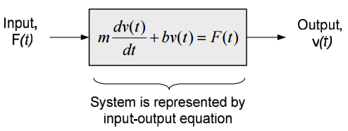
Consider the mass-damper system shown in the figure below. The applied force F(t) pushes the mass to the right. The mass's velocity resulting from the applied force is v(t). The mass slides on a surface with sliding coefficient of friction b, which induces a force $F_b=bv(t)$ which opposes the mass's motion. The mass is initially at rest and the applied force is zero for time before time t=0.
The governing equation for the system (obtained by drawing a free body diagram of the mass and applying $ \sum F = ma $) is:
$$m \frac{dv \left( t \right)}{dt} + bv \left( t \right) = F \left( t \right)$$
The governing equation for the system is a first order differential equation. Knowledge of the externally applied force $F \left( t \right)$ and the initial velocity of the mass allows us to determine the velocity of the mass at all subsequent times. Thus, we can model the system as having an input signal $F \left( t \right)$ - which is known - and an output velocity $v \left( t \right)$ which can be determined from the input signal and the properties of the system (the mass, m, and coefficient of fiction, b). The system can then be represented by the block diagram below:
(It is rather unusual to place the system governing equation directly in a block diagram; we do it here to illustrate a point.)
Example 4.2: Electrical Circuit
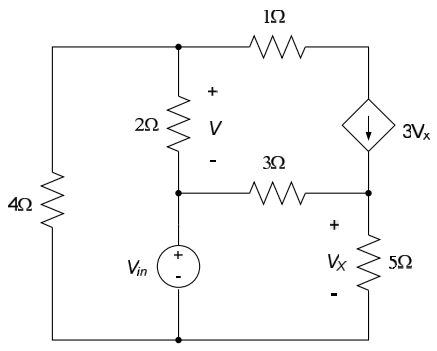
For the electrical circuit below, write the equations governing the input-output relationship for the circuit. The applied input to the circuit is the voltage source $V_{in}$ and the output is the voltage $V$ across the $2\Omega$ resistor.
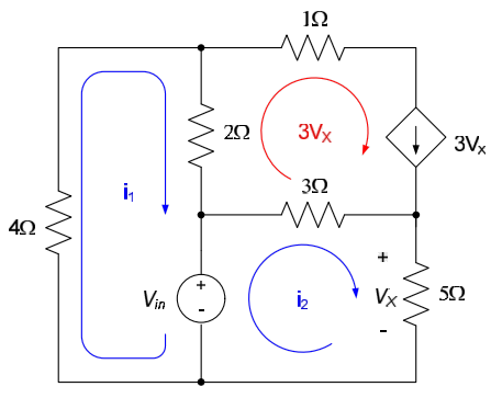
We previously wrote mesh equations for this circuit (for a specific value of $V_{in}$) in Chapter 3.2. We repeat these mesh equations here, along with our definitions of the mesh currents:
$$4i_1 + 2 \left( i_1 - 3V_X \right) + V_{in} = 0$$
$$-V_{in} +3 \left(i_2 - 3V_X \right) + 5i_2 = 0$$
$$V_X = 5i_2$$
The output voltage V is related to the mesh currents by:
$$V= 2 \left( i_1 - 3V_x \right)$$
The above four equations provide an inppot-output description of the circuit. If desired, they can be combined to eliminate all variables except $V_{in}$ and $V$ and re-written in the form $V = f \{ V_{in} \}$ per equation (1). Note that all information about the original system, except the relationship between the input and output signals, is lost once we do this.
The system-level block diagram for the circuit might then be drawn as:
Example 4.3: Temperature Control System
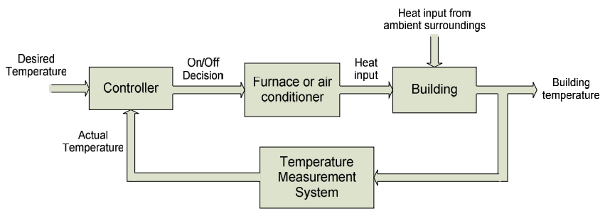
Our final example is of a temperature control system. This example illustrates the representation of a complex system as a set of interacting subsystems.
A typical temperature control system for a building will have a thermostat which allows the occupants to set a desired temperature, a furnace (or air conditioner) which provides a means of adjusting the building's temperature, some way of measuring the actual building temperature, and a controller which decides whether to turn the furnace or air conditioner on or off, based on the difference between the desired and actual temperatures. The block diagram below provides one possible approach toward interconnecting these subsystems into an overall temperature control system. This block diagram can be used to identify individual subsystems, and provide specifications for the subsystems, which can allow the design to proceed efficiently. For example:
- The temperature measurement system might be required to produce a voltage, which is a function of the temperature in the building. The thermistor-based temperature measurement systems we have designed and constructed in the lab are good examples of this type of system.
- The controller might operate by comparing the desired temperature (generally represented by a voltage level) with the voltage indicating the actual temperature. For a heating system, if the actual temperature is lower than desired by some minimum amount, the controller will make a decision to switch the furnace on. Design decisions might be made to determine what minimum temperature difference is required to turn the furnace on, and whether to base the decision to turn on the furnace strictly upon a temperature difference or on a rate of change in temperature difference.
- When the furnace turns on it will apply heat to the building, causing the building's temperature to increase. Once the building temperature is high enough, the controller will then typically turn the furnace back off. The furnace must be designed to provide appropriate heat input to the building, based on the building size and the anticipated heat losses to the building's surroundings. (For example, a larger building or a building in a colder climate will require a larger furnace.)
- A model of the building's heat losses will generally be necessary in order to size the furnace correctly and choose an appropriate control scheme. Design choices for the building itself may include insulation requirements necessary to satisfy desired heating costs.
Designs for the above subsystems can now proceed somewhat independently, with proper coordination between the design activities.
Section Summary
- Systems are a set of components which work together to perform some task. Systems are typically considered to have one or more inputs (which are provided to the system from the external environment) and one or more outputs (which the system provides to the environment).
- Generically, the inputs and outputs of systems are signals. Signals are simply time-varying functions. They can be voltages, currents, velocities, pressures, etc.
- Systems are often characterized by their input-output equations. The input-output equation for a system simply provides a mathematical relationship between the input to the system and the output from the system. Once the input is defined as a particular number or function of time, that value or function can be substituted into the input-output equation to determine the system's response to that input.
Exercises
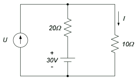
1. The input to the circuit below is the current, U. The output is the current through the $10\Omega$ resistor, I. Determine an input-output equation for the circuit.
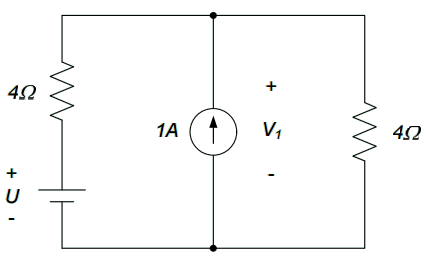
2. The input to the circuit is the voltage U. The output is the voltage $V_1$. Determine an input-output relation for the circuit.
4.2: Linear Systems
We have so far introduced a number of approaches for analyzing electrical circuits, including: Kirchhoff's current law, Kirchhoff's voltage law, circuit reduction techniques, nodal analysis, and mesh analysis. When we have applied the above analysis methods, we have generally assumed that any circuit elements operate linearly. For example, we have used Ohm's law to model the voltage-current relationship for resistors. Ohm's law is applicable only for linear resistors - that is, for resistors whose voltage-current relationship is a straight line described by the equation $v=Ri$. Non-linear resistors have been mentioned briefly; in Lab Assignment 1, for example, we forced a resistor to dissipate an excessive amount of power, thereby causing the resistor to burn out and display nonlinear operating characteristics. All circuit elements will display some degree of non-linearity, at least under extreme operating conditions.
Unfortunately, the analysis of non-linear circuits is considerably more complicated than analysis of linear circuits. Additionally, in subsequent chapters we will introduce a number of analysis methods which are applicable only to linear circuits. The analysis of linear circuits is thus very pervasive - for example, designing linear circuits is much simpler than the design of non-linear circuits. For this reason, many non-linear circuits are assumed to operate linearly for design purposes; non-linear effects are accounted for subsequently during design validation and testing phases.
The concept of treating an electrical circuit as a system was introduced in section 4.1. In systems-level analysis of circuits, we are primarily interested in the relationship between the system’s input and output signals. Circuits governed by nonlinear equations are considered to be nonlinear systems; circuits whose governing input-output relationship is linear are linear systems. In this chapter, we formally introduce the concept of linear systems. The analysis of linear systems is extremely common, for the reasons mentioned above: structural systems, fluid dynamic systems, and thermal systems are often analyzed as linear systems, even though the underlying processes are often inherently nonlinear. Linear circuits are a special case of linear systems, in which the system consists only of interconnected electrical circuit elements whose voltage-current relationships are linear.
Linear systems are described by linear relations between dependent variables. For example, the voltage-current characteristic of a linear resistor is provided by Ohm’s law:
$$v=R \cdot i$$
Where v is the voltage drop across the resistor, i is the current through the resistor, and R is the resistance of the resistor. Thus, the dependent variables – current and voltage – are linearly related. Likewise, the equations we have used to describe dependent sources (provided in section 1.2):
- Voltage controlled voltage source: $v_s = \mu v_1$
- Voltage controlled current source: $i_s = gv_1$
- Current controlled voltage source: $v_s = ri_1$
- Current controlled current source: $i_s = \beta i_1$
All describe linear relationships between the controlled and controlling variables.
All of the above relationships are of the form:
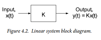
$$y(t) = Kx(t) \qquad (Eq. 4.2)$$
Where $x(t)$ and $y(t)$ are voltages or currents in the above examples. More generally, $x(t)$ and $y(t)$ can be considered to be the input and output signals, respectively, of a linear system. Equation 4.2 is often represented in block diagram form as shown in Figure 4.2.
The output is sometimes called the response of the system to the input. The multiplicative factor K relating the input and output is often called the system’s gain. Elements which are characterized by relationships of the form of equation 4.2 are sometimes called linear elements. The equation relating the system’s input and output variables is called the input-output relationship of the system.
Aside:
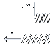
Many types of systems can be described by the relationship of equation (1). For example, Hooke’s law, which relates the force applied to a spring to the spring’s displacement, is:
$$F = k \cdot \Delta x$$
Where $k$ is the spring constant, $F$ is the applied force, and $\Delta x$ is the resulting displacement as shown below. In this example, $F$ is the input to the system and $\Delta x$ is the system output.
Notice that we have allowed the input and output of our system to vary as functions of time. Constant values are special cases of time-varying functions. We will assume that the system gain is not a time-varying quantity.
For our purposes, we will define linearity in somewhat more broad terms than equation (4.2). Specifically, we will define a system as linear if it satisfies the following requirements:
Linearity:
- If the response of a system to some input $x_1(t)$ is $y_1(t)$ then the response of the system to some input $\alpha x_1(t)$ is $\alpha y_1(t)$, where $\alpha$ is some constant. This property is called homogeneity.
- If the response of the same system to an input $x_2(t)$ is $y_2(t)$, then the response of the system to an input $x_1(t)+x_2(t)$ is $y_1(t)+y_2(t)$. This is called the additive property.
The above two properties defining a linear system can be combined into a single statement, as follows: if the response of a system to an input $x_1(t)$ is $y_1(t)$ and the system’s response to an input $x_2(t)$ is $y_2(t)$, then the response of the system to an input $\alpha x_1(t)+\alpha x_2(t)$ is $\alpha y_1(t)+\alpha y_2(t)$. This property is illustrated by the block diagram of Figure 4.3. The Sigma symbol in Figure 4.3 denotes signal summation; the signs on the inputs to the summation block indicate the signs to be applied to the individual signals.
The above definition of linearity is more general than the expression of equation (4.2). For example, the processes of differentiation and integration are linear processes according to the above definition. Thus, systems with the input-output relations such as:
$$y = a \int adt$$ and $$y = b \frac{dx}{dt}$$
are linear systems. We will use circuit elements which perform integrations and differentiations later when we discuss energy storage elements such as capacitors and inductors.
Dependent Variables and Linearity:
Linearity is based on the relationships between dependent variables, such as voltage and current. In order for a system to be linear, relationships between dependent variables must be linear – plots of one dependent variable against another are straight lines. This causes confusion among some readers when we begin to talk about time varying signals. Time is not a dependent variable, and plots of voltages or currents as a function of time for a linear system may not be straight lines.
Although the above definitions of linear systems are fundamental, we will not often use them directly. Kirchhoff’s voltage law and Kirchhoff’s current law rely upon summing multiples of voltages or currents. As long as the voltage-current relations for individual circuit elements are linear, application of KVL and KCL to the circuit will result in linear equations for the system. Therefore, rather than direct application of the above definitions of linear systems, we will simply claim that an electrical circuit containing only linear circuit elements will be linear and will have linear input-output relationships. All circuits we have analyzed so far have been linear.
Linearity:
If all elements in a circuit have linear voltage-current relationships, the overall circuit will be linear.
Important Note About Power:
A circuit’s power is not a linear property, even if the voltage-current relations for all circuit elements are linear. Resistors which obey Ohm’s law dissipate power according to $P = iv = \frac{v^2}{R} = i^2 R$. Thus, the power dissipation of a linear resistor is not a linear combination of voltages or currents – the relationship between voltage or current and power is quadratic. Thus, if power is considered directly in the analysis of a linear circuit, the resulting system is nonlinear.
Section Summary
- Linear systems are characterized by linear relationships between dependent variables in the system. For electrical system, this typically means that the relationship between voltage and current for any circuit component is linear – in electrical circuits, for example, this means that a plot of voltage vs. current for every element in the system is a straight line. Ohm’s law, for example, describes a linear voltage-current relationship.
- Linear systems have a very important property: the additive principle applies to them. Superposition essentially means that the response of a system to some combination of inputs $x_1+x_2$ will be the same as the sum of the response to the individual inputs $x_1$ and $x_2$.
Exercises
1. The 20Ω resistor below obeys Ohm’s law, so that $V=20I$. We will consider the input to be the current through the resistor and the output to be the voltage drop across the resistor. Determine:
- The output V if the input $I=2A$.
- The output V if the input $I = 3A$.
- The output V is the input $I = 2A + 3A = 5A$
Do your answers above indicate that the additive property holds for this resistor? Why?
2. A linear electrical circuit has an input voltage $V_1$ and provides an output voltage $V_2$, as indicated in the block diagram below. If an input voltage $V_1 = 3V$ is applied to the circuit, the measured output voltage $V_2 = 2V$. What is the output voltage if an input voltage $V_1=6V$ is applied to the circuit?
4.3: Superposition
In section 4.2, we stated that, by definition, the input-output relations for linear systems have an additive property. The additive property of linear systems states that:
- If the response of a system to an input $x_1(t)$ is $y_1(t)$ and the response of the system to an input $x_2(t)$ is $y_2(t)$, then the response of the system to an input $x_1(t)+ x_2(t)$ is $y_1(t)+y_2(t)$.
Thus, if a system has multiple inputs, we can analyze the system’s response to each input individually and then obtain the overall response by summing the individual contributions. This property can be useful in the analysis of circuits which have multiple sources. If we consider the sources in a circuit to be the inputs, linear circuits with multiple independent sources can be analyzed by determining the circuit’s response to each source individually, and then summing, or superimposing, the contributions from each source to obtain the overall response of the circuit to all sources. In general, the approach is to analyze a complicated circuit with multiple sources by determining the responses of a number of simpler circuits – each of which contains only a single source.
We illustrate the overall approach graphically by the block diagram of Figure 4.4 (which is really just a reversed form of the block diagram of Figure 4.3).
In Figure 4.4, we have a linear system with two input signals which are applied by sources in the circuit. We can analyze this circuit by noting that each input signal corresponds to an independent source in the circuit. Thus, if the circuit’s overall response to a source $x_1(t)$ is $y_1(t)$ and the circuit’s response to a source $x_2(t)$ is $y_2(t)$, then the total circuit response will be the sum of the two individual responses, $y_1(t) + y_2(t)$. Thus, if we wish to determine the response of the circuit to both sources, $x_1(t)$ and $x_2(t)$, we can determine the individual responses of the circuit, $y_1(t)$ and $y_2(t)$ and then sum (or superimpose) the responses to obtain the circuit’s overall response to both inputs. This analysis method is called superposition.
In order to determine a circuit’s response to a single source, all other independent sources must be turned off (or, in more colorful terminology, killed, or made dead). To turn off a current source, we must make the input current zero, which corresponds to an open circuit. To turn off a voltage source, we must make the input voltage zero, which corresponds to a short circuit.
Killing Sources:
- To kill a voltage source, replace it with a short circuit
- To kill a current source, replace it with an open circuit
To apply the superposition method, then, the circuit’s response to each source in the circuit is determined, with all other sources in the circuit dead. The individual responses are then algebraically summed to determine the total response to all inputs. To illustrate the method, we consider the examples below.
Example 4.4
Determine the voltage, $V$, in the circuit below, using superposition.
The circuit above can be considered to be the superposition of the two circuits shown below, each with a single source (the other source, in both cases, has been killed).
The voltage $V_1$ above can be determined to be the result of a current division: $V_1 = \left[ \frac{1 \Omega} {1\Omega + 2\Omega} \cdot 3A \right] \times 2\Omega = 2V$.
$V_2$ can be determined to be the result of a voltage division: $V_1 = 12V \cdot \frac{2\Omega}{2\Omega + 1\Omega} = 8V$. Thus, the voltage $V=V_1 + V_2 = 10V$.
Example 4.5
Determine the voltage, $V$, in the circuit below, using superposition.
We begin by determining the response $V_1$ to the 6V source by killing the 2A source, as shown in the figure below.
The voltage $V_1$ is simply the result of a voltage division: $V_1 = \frac{1}{2} \cdot 6V = 2V$. The response $V_2$ to the 2A source can be determined by killing the 6V source, resulting in the circuit below:
Killing the 6V source places a short circuit in parallel with the 2A source, so no voltage is induced in any of the resistors by the 2A source. Thus, $V_2=0V$.
The voltage $V$ is the sum of the two individual voltages: $V=V_1 +V_2 = 2V + 0V =2V$
Notes on Superposition:
- Superposition cannot be used directly to determine power. Previously, we noted that power is not governed by a linear relationship. Thus, you cannot determine the power dissipated by a resistor by determining the power dissipation due to each source and then summing the results. You can, however, use superposition to determine the total voltage or current for the resistor and then calculate the power from the voltage and/or current.
- When using superposition to analyze circuits with dependent sources, do not kill the dependent sources. You must include the effects of the dependent sources in response to each independent source.
- Superposition is a powerful circuit analysis tool, but its application can result in additional work. Before applying superposition, examine the circuit carefully to ensure that an alternate analysis approach is not more efficient. Circuits with dependent sources, in particular, tend to be difficult to analyze using superposition.
Section Summary
- Superposition is a defining property of linear systems. It essentially means that, for linear systems, we can decompose any input to the system into a number of components, determine the system output resulting from each component of the input, and obtain the overall output by summing up these individual components of the output.
- Superposition can be used directly to analyze circuits which contain multiple independent sources. The responses of the circuit to each source (killing all other sources) are determined individually. The overall response of the circuit – due to all sources – is then obtained by summing (superimposing) these individual contributions.
- The principle of superposition is a fundamental property of linear systems and has very broad-ranging consequences. We will be invoking it throughout the remainder of this textbook, often without overtly stating that superposition is being used. The fact that superposition applies to linear circuits is the basic reason why engineers make every possible attempt to use linear models when analyzing and designing systems.
Exercises
4.4: Two-terminal Networks
As noted in section 4.1, it is often desirable, especially during the design process, to isolate different portions of a complex system and treat them as individual subsystems. These isolated subsystems can then be designed or analyzed somewhat independently of one another and subsequently integrated into the overall system in a top- down design approach. In systems composed of electrical circuits, the subsystems can often be represented as two-terminal networks. As the name implies, two-terminal networks consist of a pair of terminals; the voltage potential across the terminals and the current flow into the terminals characterizes the network. This approach is consistent with our systems-level approach; we can characterize the behavior of what may be an extremely complex circuit by a relatively simple input-output relationship.
We already have some experience with two-terminal networks; when we determined equivalent resistances for series and parallel resistor combinations, we treated the resistive network as a two-terminal network. For analysis purposes, the network was then replaced with a single equivalent resistance which was indistinguishable from the original circuit by any external circuitry attached to the network terminals. In this chapter, we will formalize some two-terminal concepts and generalize our approach to include networks which contain both sources and resistors.
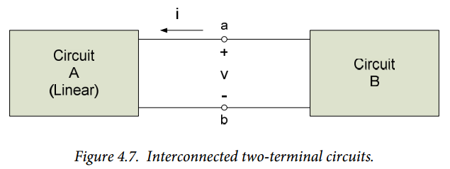
We will assume that the electrical circuit of interest can be subdivided into two sub-circuits, interconnected at two terminals, as shown in Figure 4.5. Our goal is to replace circuit A in our overall system with a simpler circuit which is indistinguishable by circuit B from the original circuit. That is, if we disconnect circuit A from circuit B at the terminals and replace circuit A with its equivalent circuit, the voltage $v$ and the current $i$ seen at the terminals of the circuits will be unchanged and circuit B’s operation will be unaffected. In order to make this substitution, we will need to use the principle of superposition in our analysis of circuit A – thus, circuit A must be a linear circuit. We are not changing circuit B in any way – circuit B can be either linear or nonlinear.
It should be emphasized that circuit A is not being physically changed. We are making the change conceptually in order to simplify our analysis of the overall system. For example, the design of circuit B can now proceed with a simplified model of circuit A’s operation, perhaps before the detailed design of circuit A is even finalized. When the designs of the two circuits are complete, they can be integrated and the overall system has a high probability of functioning as expected.
In order to perform the above analysis, we will disconnect the two sub-circuits in Figure 4.5 at the terminals a – b and determine the current-voltage relationship at the terminals of circuit A. We will generally refer to circuit A’s current-voltage relationship as its i-v characteristic. Our approach, therefore, is to look at circuit A alone, as shown in Figure 4.6, and determine the functional relationship between a voltage applied to the terminals and the resulting current. (Equivalently, we could consider that a current is applied at the terminals and look at the resulting voltage.) Figure 4.6 is at first glance somewhat misleading – the terminals should not be considered to be open-circuited, as a cursory look at the figure might indicate; we are determining the relationship between a voltage difference applied to the circuit and the resulting current flow. (Figure 4.6 indicates a current I flowing into the circuit, which will, in general, not be zero.)
System-level Interpretation
When we determine the i-v characteristic for the circuit, we are determining the input-output relationship for a system. Either the voltage or the current at the terminals can be viewed as the input to a system; the other parameter is the output. The i-v characteristic then provides the output of the system as a function of the input.
Resistive Networks
We have already (somewhat informally) treated purely resistive circuits as two-terminal networks when we determined equivalent resistances for series and parallel resistors. We will briefly review these concepts here in a systems context in terms of a simple example.
Example 4.6
Determine the i-v characteristic for the circuit below.
Previously, we would use circuit reduction techniques to solve this problem. The equivalent resistance is $R_{eq} = 2\Omega + \frac{\left( 3\Omega \right) \cdot \left( 6\Omega \right)}{3\Omega + 6\Omega} = 4\Omega$. Since $v=R_{eq} i$, the circuit's i-v characteristic is $v=4i$.
We would now, however, like to approach this problem in a slightly more general way and using a systems-level view to the problem. Therefore, we will choose the terminal voltage, v, to be viewed as the input to the circuit. By default, this means the current i will be our circuit’s output. (We could, just as easily define the current as the input, in which case the voltage would become our output.) Thus, our circuit conceptually looks like a system as shown in the block diagram below.
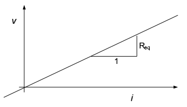
Applying KCL to node c in the above circuit results in $i = \frac{v_c}{6\Omega} + \frac{v_c}{3\Omega}$. Ohm's law, applied to the $2\Omega$ resistors, results in $v-v_c = 2\Omega \cdot i$. Eliminating $v_c$ from the above two equations results in $v=4i$, which is the same result we obtained using circuit reduction. The i-v characteristic for the above circuit is shown graphically below; the slope of the line is simply the equivalent resistance of the network.
In the above example, viewing the circuit as a general two-terminal network and using a more general systems-level approach to the problem results in additional work relative to using our previous circuit reduction approach. Viewing the circuit as a more general two-terminal network is, however, very profitable if circuit reduction techniques are not applicable or if we allow the circuit to contain voltage or current sources. The latter topic is addressed in the following subsection.
Two-terminal Networks with Sources
When the network consists of resistive elements and independent sources, the circuit’s i-v characteristic can be represented as a single equivalent resistance and a single source-like term. In general, however, we cannot determine this directly by using circuit reduction techniques. The overall approach and typical results are illustrated in the following examples.
Example 4.7
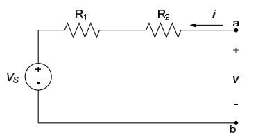
Determine the i-v characteristic of the circuit below.
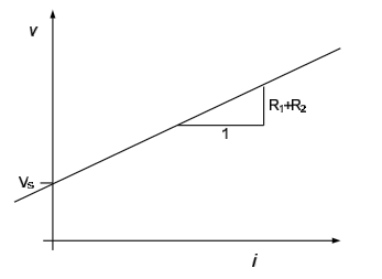
Although it is fairly apparent, by applying Ohm's law across the series combination of resistors, that $v= \left( R_1 + R_2 \right) i + V_S$, we will (for practice) use superposition to approach this problem. The voltage source $V_s$ will, of course, be one source in the circuit. We will use the voltage across the terminals a-b as a second source in the circuit.
Killing the voltage source $V_s$ results in the circuit to the left below; the resulting current is $i_1 = \frac{v}{R_1 + R_2}$. Killing the “source” v results in the circuit to the right below; the resulting current is $i_2 = -\frac{V_S}{R_1+R_2}$. The total current is, therefore, $i= \frac{v}{R_1 + R_2} - \frac{V_S}{R_1 + R_2}$ or $v= \left(R_1 + R_2 \right) i + V_S$.
Plotting the above i-v characteristic results in the figure below.
Example 4.8
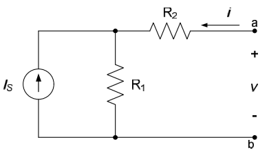
Determine the i-v characteristic of the circuit below.
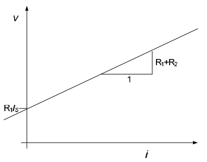
Although not the most efficient approach for this problem, we will again use superposition to approach the problem. One source will, of course, be the current source $I_S$. We will assume that our second source is the current $i$ at node a. Killing the current source $I_S$ results in the circuit to the left below; from this figure the voltage $v_1$ can be seen to be $v_1 = i \left( R_1 + R_2 \right)$. Killing the current source $i$ results in the figure to the right below; from this figure the voltage $v_2$ is seen to be $v_2 = R_1I_S$ (the dead current source results in an open circuit, so no current flows through the resistor $R_2$). The total voltage across the terminals is, therefore, $v= \left( R_1 + R_2 \right) i + R_1I_S$.
The i-v characteristic for the circuit is, therefore, as shown in the figure below.
Notes on Linear Circuit i-v Characteristics:
- All two-terminal networks which contain only sources and resistors will have i-v relationships of the form shown in examples 1, 2, and 3. That is, they will be straight lines of the form $v=m \cdot i + b$. The y-intercept term, b, is due to sources in the network; if there are no sources in the network, $b = 0$ and the i-v characteristic will pass through the origin.
- Due to the form of the i-v characteristic provided in note 1 above, any two-terminal network can be represented as a single source and a single resistor.
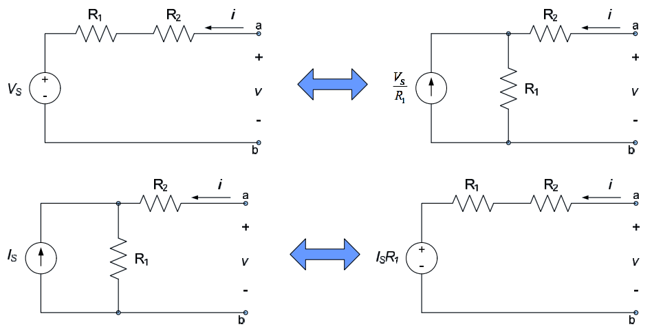
- The form of the solution for examples 2 and 3 are the same. Thus, the circuit of example 2 is indistinguishable from a similar circuit with a current source $\frac{V_S}{R_1}$ in parallel with the resistor $R_1$. Likewise, the circuit of example 3 is indistinguishable from a similar circuit with a voltage source $I_SR_1$ in series with the resistor $R_1$. The equivalent circuits are shown below.
Section Summary
- Electrical circuits, sub-circuits, and components are often modeled by the relationship between voltage and current at their terminals. For example, we are familiar with modeling resistors by Ohm’s law, which simply relates the voltage to the current at the resistor terminals. In Chapter 2, we used circuit reduction methods to extend this concept by replacing resistive networks with equivalent resistances which provided the same voltage-current relations across their terminals. In this section, we continue to extend this concept to circuits which include sources.
- For linear circuits, the voltage-current relationship across two terminals of the circuit can always be represented as a straight line of the form $v=m \cdot i + b$. If we plot this relationship with voltage on the vertical axis and current on the horizontal axis, the slope of the line corresponds to an equivalent resistance seen across the terminals, while the y-intercept of the line is the voltage across the terminals, if the terminals are open-circuited. We will formalize this important result in section 4.5.
Exercises
4.5: Thévenin’s and Norton’s Theorems
In section 4.4, we saw that it is possible to characterize a circuit consisting of sources and resistors by the voltage- current (or i-v) characteristic seen at a pair of terminals of the circuit. When we do this, we have essentially simplified our description of the circuit from a detailed model of the internal circuit parameters to a simpler model which describes the overall behavior of the circuit as seen at the terminals of the circuit. This simpler model can then be used to simplify the analysis and/or design of the overall system.
In this section, we will formalize the above result as Thévenin’s and Norton’s theorems. Using these theorems, we will be able to represent any linear circuit with an equivalent circuit consisting of a single resistor and a source. Thévenin’s theorem replaces the linear circuit with a voltage source in series with a resistor, while Norton’s theorem replaces the linear circuit with a current source in parallel with a resistor. In this section, we will apply Thévenin’s and Norton’s theorems only to purely resistive networks. However, these theorems can be used to represent any circuit made up of linear elements.
Consider the two interconnected circuits shown in Figure 4.7 below. The circuits are interconnected at the two terminals a and b, as shown. Our goal is to replace circuit A in the system of Figure 4.7 with a simpler circuit which has the same current-voltage characteristic as circuit A. That is, if we replace circuit A with its simpler equivalent circuit, the operation of circuit B will be unaffected. We will make the following assumptions about the overall system:
- Circuit A is linear
- Circuit A has no dependent sources which are controlled by parameters within circuit B
- Circuit B has no dependent sources which are controlled by parameters within circuit A
In section 4.3, we determined i-v characteristics for several example two-terminal circuits, using the superposition principle. We will follow the same basic approach here, except for a general linear two-terminal circuit, in order to develop Thévenin’s and Norton’s theorems.
Thévenin’s Theorem
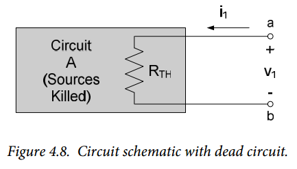
First, we will kill all sources in circuit A and determine the voltage resulting from an applied current, as shown in Figure 4.8 below. With the sources killed, circuit A will look strictly like an equivalent resistance to any external circuitry. This equivalent resistance is designated as $R_{TH}$ in Figure 4.8. The voltage resulting from an applied current, with circuit A dead is:
$$v_1 = R_{TH} \cdot i \qquad (Eq. 4.3)$$
Now we will determine the voltage resulting from re-activating circuit A’s sources and open-circuiting terminals a and b. We open-circuit the terminals a-b here since we presented equation (4.3) as resulting from a current source, rather than a voltage source. The circuit being examined is as shown in Figure 4.9. The voltage $v_{OC}$ is the “open-circuit” voltage.
Superimposing the two voltages above results in:
$$v=v_1 + v_{OC} \qquad (Eq. 4.4)$$
Or
$$v= R_{TH} \cdot i + v_{OC} \qquad (Eq. 4.5)$$
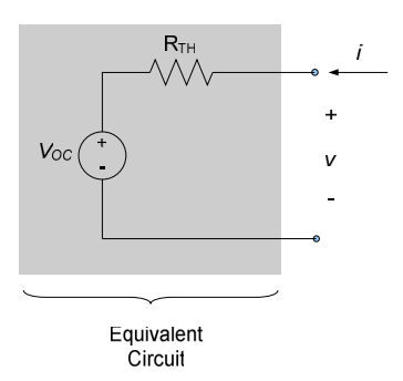
Equation (4.5) is Thévenin’s theorem. It indicates that the voltage-current characteristic of any linear circuit (with the exception noted below) can be duplicated by an independent voltage source in series with a resistance $R_{TH}$, known as the Thévenin resistance. The voltage source has the magnitude $v_{OC}$ and the resistance is $R_{TH}$, where $v_{OC}$ is the voltage seen across the circuit’s terminals if the terminals are open-circuited and $R_{TH}$ is the equivalent resistance of the circuit seen from the two terminals, with all independent sources in the circuit killed. The equivalent Thévenin circuit is shown in Figure 4.10.
Procedure for Determining Thévenin Equivalent Circuit
- Identify the circuit and terminals for which the Thévenin equivalent circuit is desired.
- Kill the independent sources (do nothing to any dependent sources) in circuit and determine the equivalent resistance RTH of the circuit. If there are no dependent sources, $R_{TH}$ is simply the equivalent resistance of the resulting resistive network. Otherwise, one can apply an independent current source at the terminals and determine the resulting voltage across the terminals; the voltage-to-current ratio is $R_{TH}$.
- Re-activate the sources and determine the open-circuit voltage $V_{OC}$ across the circuit terminals. Use any analysis approach you choose to determine the open-circuit voltage.
Example 4.9
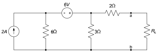
Determine the Thévenin equivalent of the circuit below, as seen by the load, $R_L$.
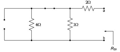
We want to create a Thévenin equivalent circuit of the circuit to the left of the terminals a-b. The load resistor, $R_L$, takes the place of “circuit B” in Fig. 1. The circuit has no dependent sources, so we kill the independent sources and determine the equivalent resistance seen by the load. The resulting circuit is shown below.
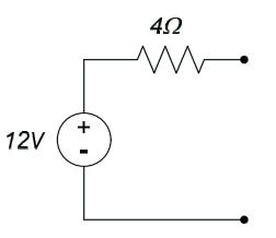
From the above figure, it can be seen that the Thévenin resistance $R_{TH}$ is a parallel combination of a $3\Omega$ resistor and a $6\Omega$ resistor, in series with a $2\Omega$ resistor. Thus, $R_{TH} = \frac{\left( 6\Omega \right) \left( 3\Omega \right)}{6\Omega + 3\Omega} + 2\Omega = 4\Omega$.
The open-circuit voltage $v_{OC}$ is determined from the circuit below. We (arbitrarily) choose nodal analysis to determine the open-circuit voltage. There is one independent voltage in the circuit; it is labeled as $v_0$ in the circuit below. Since there is no current through the $2\Omega$ resistor, $v_{OC} = v_0$.
Applying KCL at $v_0$, we obtain: $-2A + \frac{v_0 - 6V}{6\Omega} + \frac{v_0}{3\Omega} = 0 \Rightarrow v_0 = v_{OC} = 6V$. Thus, the Thévenin equivalent circuit is on the left below. Re-introducing the load resistance, as shown on the right below, allows us to easily analyze the overall circuit.
Norton’s Theorem
The approach toward generating Norton’s theorem is almost identical to the development of Thévenin’s theorem, except that we apply superposition slightly differently. In Thévenin’s theorem, we looked at the voltage response to an input current; to develop Norton’s theorem, we look at the current response to an applied voltage. The procedure is provided below.
Once again, we kill all sources in circuit A, as shown in Figure 4.8 above but this time we determine the current resulting from an applied voltage. With the sources killed, circuit A still looks like an equivalent resistance to any external circuitry. This equivalent resistance is designated as $R_{TH}$ in Figure 4.8. The current resulting from an applied voltage, with circuit A dead is:
$$i_1 = \frac{v}{R_{TH}} \qquad (Eq. 4.6)$$
Notice that equation (4.6) can be obtained by rearranging equation (4.3).
Now we will determine the current resulting from re-activating circuit A’s sources and short-circuiting terminals a and b. We short-circuit the terminals a-b here since we presented equation (4.4) as resulting from a voltage source. The circuit being examined is as shown in Figure 4.11. The current $i_{SC}$ is the “short-circuit” current. It is typical to assume that under short-circuit conditions the short-circuit current enters the node at a; this is consistent with an assumption that circuit A is generating power under short-circuit conditions.
Employing superposition, the current into the circuit is (notice the negative sign on the short-circuit current, resulting from the definition of the direction of the short-circuit current opposite to the direction of the current i).
$$i = i_1 - i_{SC} \qquad (Eq. 4.7)$$
So
$$i = \frac{v}{R_{TH}} - i_{SC} \qquad (Eq. 4.8)$$
Equation (4.8) is Norton’s theorem. It indicates that the voltage-current characteristic of any linear circuit (with the exception noted below) can be duplicated by an independent current source in parallel with a resistance. The current source has the magnitude $i_{SC}$ and the resistance is $R_{TH}$, where $i_{SC}$ is the current seen at the circuit’s terminals if the terminals are short-circuited and $R_{TH}$ is the equivalent resistance of the circuit seen from the two terminals, with all independent sources in the circuit killed. The equivalent Norton circuit is shown in Fig. 4.12.
Procedure for Determining Norton Equivalent Circuit:
- Identify the circuit and terminals for which the Norton equivalent circuit is desired.
- Determine the equivalent resistance $R_{TH}$ of the circuit. The approach for determining $R_{TH}$ is the same for Norton circuits as Thévenin circuits.
- Re-activate the sources and determine the short-circuit current $i_{SC}$ across the circuit terminals. Use any analysis approach you choose to determine the short-circuit current.
Example 4.10
Determine the Norton equivalent of the circuit seen by the load, $R_L$, in the circuit below.
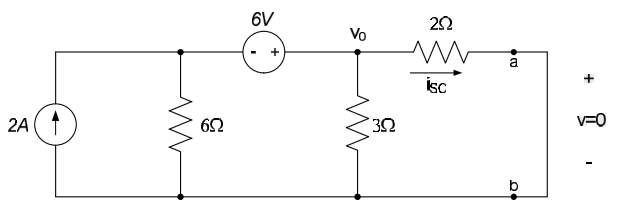
This is the same circuit as our previous example. The Thévenin resistance, $R_{TH}$, is thus the same as calculated previously: $R_{TH} = 4\Omega$. Removing the load resistance and placing a short-circuit between the nodes a and b, as shown below, allows us to calculate the short-circuit current, $i_{SC}$.
Performing KCL at the node $v_0$, results in:
$$\frac{v_0}{2\Omega} + \frac{v_0 - 6V}{6\Omega} + \frac{v_0}{3\Omega} = 2A$$
So
$$v_0 = 3V$$
Ohm's law can then be used to determine $i_{SC}$:
$$i_{SC} = \frac{3V}{2\Omega} = 1.5A$$
And the Norton equivalent circuit is shown on the left below. Replacing the load resistance in the equivalent overall circuit is shown to the right below.
Exceptions:
Not all circuits have Thévenin and Norton equivalent circuits. Exceptions are:
- An ideal current source does not have a Thévenin equivalent circuit. (It cannot be represented as a voltage source in series with a resistance.) It is, however, its own Norton equivalent circuit.
- An ideal voltage source does not have a Norton equivalent circuit. (It cannot be represented as a current source in parallel with a resistance.) It is, however, its own Thévenin equivalent circuit.
Source Transformations
Circuit analysis can sometimes be simplified by the use of source transformations. Source transformations are performed by noting that Thévenin’s and Norton’s theorems provide two different circuits which provide essentially the same terminal characteristics. Thus, we can write a voltage source which is in series with a resistance as a current source in parallel with the same resistance, and vice-versa. This is done as follows.
Equations (4.5) and (4.8) are both representations of the i-v characteristic of the same circuit. Rearranging equation (4.5) to solve for the current i results in:
$$i = \frac{v}{R_{TH}} - \frac{v_{OC}}{R_{TH}} (Eq. 4.9)$$
Equating equations (4.8) and (4.9) leads to the conclusion that:
$$i_{SC} = \frac{v_{OC}}{R_{TH}} (Eq. 4.10)$$
Likewise, rearranging equation (4.8) to obtain an expression for v gives:
$$v=i \cdot R_{TH} + i_{SC} \cdot R_{TH} (Eq. 4.11)$$
Equating equations (4.11) and (4.5) results in:
$$V_{OC} = i_{SC} \cdot R_{TH} (Eq. 4.12)$$
Which is the same result as equation (4.10).
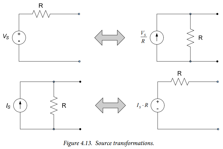
Equations (4.10) and (4.12) lead us to the conclusion that any circuit consisting of a voltage source in series with a resistor can be transformed into a current source in parallel with the same resistance. Likewise, a current source in parallel with a resistance can be transformed into a voltage source in series with the same resistance. The values of the transformed sources must be scaled by the resistance value according to equations (4.10) and (4.12). The transformations are depicted in Figure 4.13.
Source transformations can simplify the analysis of some circuits significantly, especially circuits which consist of series and parallel combinations of resistors and independent sources. An example is provided below.
Example 4.11
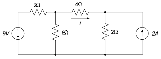
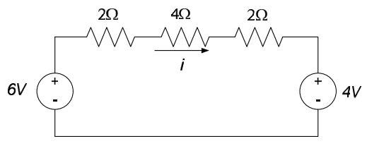
Determine the current i in the circuit shown below.
We can use a source transformation to replace the 9V source and $3\Omega$ resistor series combination with a 3A source in parallel with a $3\Omega$ resistor. Likewise, the 2A source and $2\Omega$ resistor parallel combination can be replaced with a 4V source in series with a $2\Omega$ resistor. After these transformations have been made, the parallel resistors can be combined as shown in the figure below.
The 3A source and $2\Omega$ resistor parallel combination can be combined to a 6V source in series with a $2\Omega$ resistor, as shown below.
The current i can now be determined by direct application of Ohm’s law to the three series resistors, so that $i= \frac{6V - 4V}{2\Omega + 4\Omega + 2\Omega} = 0.25A$.
Voltage-current Characteristics of Thévenin and Norton Circuits
Previously, in section 4.4, we noted that the i-v characteristics of linear two-terminal networks containing only sources and resistors are straight lines. We now look at the voltage-current characteristics in terms of Thévenin and Norton equivalent circuits.
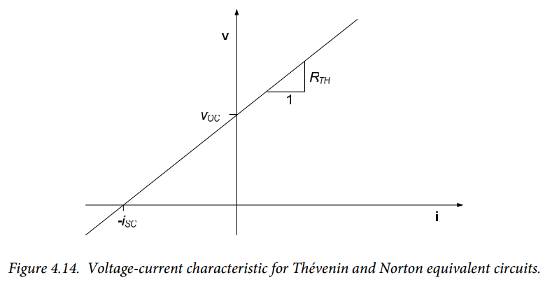
Equations (4.5) and (4.8) both provide a linear voltage-current characteristic as shown in Figure 4.14. When the current into the circuit is zero (open-circuited conditions), the voltage across the terminals is the open-circuit voltage, $v_{OC}$. This is consistent with equation (4.5), evaluated at $i = 0$:
$$v= R_{TH} \cdot i_{OC} + v_{OC} = R_{TH} \cdot 0 + v_{OC} = v_{OC}$$
Likewise, under short-circuited conditions, the voltage differential across the terminals is zero and equation (4.8) readily provides:
$$i= \frac{v_{SC}}{R_{TH}} - i_{sc} = \frac{0}{R_{TH}} - i_{sc} = - i_{sc}$$
Which is consistent with Fig. 4.14.
Figure 4.14 is also consistent with equations (4.10) and (4.12) above, since graphically the slope of the line is obviously $R_{TH} = \frac{v_{OC}}{i_{SC}}$.
Figure 4.14 also indicates that there are three simple ways to create Thévenin and Norton equivalent circuits:
- Determine $R_{TH}$ and $v_{OC}$. This provides the slope and y-intercept of the i-v characteristic. This approach is outlined above as the method for creating a Thévenin equivalent circuit.
- Determine $R_{TH}$ and $i_{SC}$. This provides the slope and x-intercept of the i-v characteristic. This approach is outlined above as the method for creating a Norton equivalent circuit.
- Determine $v_{OC}$ and $i_{SC}$. The equivalent resistance $R_{TH}$ can then be calculated from $R_{TH} = \frac{v_{OC}}{i_{SC}}$ to determine the slope of the i-v characteristic. Either a Thévenin or Norton equivalent circuit can then be created. This approach is not commonly used, since determining $R_{TH}$ – the equivalent resistance of the circuit – is usually easier than determining either $v_{OC}$ or $i_{SC}$.
Note:
It should be emphasized that the Thévenin and Norton circuits are not independent entities. One can always be determined from the other via a source transformation. Thévenin and Norton circuits are simply two different ways of expressing the same voltage-current characteristic.
Section Summary
- Thévenin’s theorem allows us to replace any linear portion of a circuit with equivalent circuit consisting of a voltage source in series with a resistance. This circuit is called the Thévenin equivalent, and provides the same voltage-current relationship at the terminals as the original circuit. The voltage source in the equivalent circuit is the same as the voltage which would be measured across the terminals of the original circuit, if those terminals were open-circuited. The resistance in the equivalent circuit is called the Thévenin resistance, it is the resistance that would be seen across the terminals of the original circuit, if all sources in the circuit were killed.
- Norton’s theorem allows us to replace any linear portion of a circuit with equivalent circuit consisting of a current source in parallel with a resistance. This circuit is called the Norton equivalent, and provides the same voltage-current relationship at the terminals as the original circuit. The current source in the equivalent circuit is the same as the current which would be measured across the terminals of the original circuit, if those terminals were short-circuited. The resistance in the equivalent circuit is the resistance that would be seen across the terminals of the original circuit, if all sources in the circuit were killed; it is the same as the Thévenin resistance.
- Thevenin and Norton’s theorems allow us to perform source transformations when analyzing circuits. This approach simply allows us to replace any voltage source which is in series with a resistance with a current source in parallel with the same resistance, and vice-versa. The relationship between the voltage and current sources used in these transformations are provided in equations (4.10) and (4.12).
Exercises
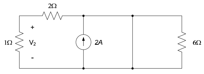
1. Replace everything except the 1A current source with its Thévenin equivalent circuit and use the result to find $V_1$.
2. Replace everything except the 1A current source with its Norton equivalent circuit and use the result to find $V_1$.
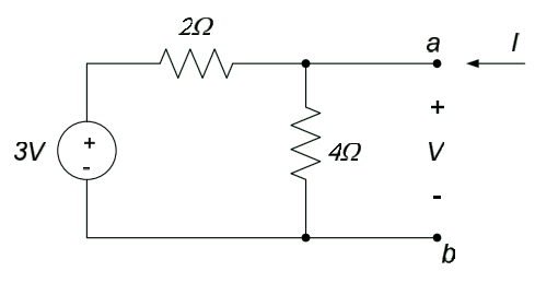
3. Determine a Norton equivalent circuit for the circuit below.
4.6: Maximum Power Transfer
It is often important for our electrical system to transfer as much power as possible to some related system. For example, in an audio system it is important that the amplifier transfer as much power as possible to the loudspeakers. Otherwise, the amplifier generates power which is not used for any productive purpose1) and the efficiency of the overall system suffers.
In this section, we will develop design guidelines which will ensure that the maximum possible amount of power is transferred from our electrical circuit to the load that the circuit is driving. These guidelines will be based on Thevenin’s theorem.
Consider the system shown in Figure 4.15. The overall system consists of an electrical circuit which is being used to drive a load. Physically, the load can be either another electrical system or some electromechanical system such as an electric motor or a loudspeaker. We will model the load as an electrical resistance, $R_L$, though the principles presented here are applicable to more general loading conditions.
We will replace our electrical system with its Thevenin equivalent in order to analyze the power delivered by the circuit to the load. The overall circuit that we are analyzing is now modeled as shown in Figure 4.16.
From Figure 4.16, the voltage delivered to the load can be readily determined from a voltage divider relation:
$$V_L = V_{OC} \frac{R_L}{R_L + R_{TH}} (Eq. 4.13)$$
Thus, the power delivered to the load is:
$$P_L = \frac{V_L^2}{R_L} = \frac{V^2_{OC}}{R_L} \left( \frac{R_L}{R_L + R_{TH}} \right) ^2 (Eq. 4.14)$$
Figure 4.17 shows a plot of the power delivered to the load, as a function of the load resistance. The power delivered to the load is zero when the load resistance is zero (since there is no voltage drop across the load under this condition) and goes to zero as the load resistance approaches infinity (since there is no current provided to the load under this condition). At some value of $R_L$ the power transfer will be maximized – our goal will be to determine the value for $R_L$ which maximizes the power delivered to the load.
The maximum value of power on the curve shown in Figure 4.17 can be determined by differentiating equation (4.14) with respect to the load resistance $R_L$ and setting the result to zero. This leads to:
$$\frac{\partial P_L}{\partial R_L} = V^2_{OC} \left[ \frac{\left( R_L + R_{TH} \right) ^2 - 2R_L \left( R_{TH} + R_L \right) }{\left( R_L + R_{TH} \right) ^4} \right] = 0 (Eq. 4.15)$$
The above condition is satisfied if the numerator of equation (4.15) is zero, so our condition becomes:
$$\left( R_L + R_{TH} \right) ^2 = 2R_L \left( R_{TH} + R_L \right) $$
Dividing both sides by $R_{TH} + R_L$ results in:
$$R_L + R_{TH} = 2R_L$$
Or
$$R_L = R_{TH} (Eq. 4.16)$$
Thus, maximum power transfer takes place when the load resistance and the Thevenin resistance of the circuit supplying the power are equal. The above result is sometimes called the maximum power transfer theorem. When the conditions of the maximum power transfer theorem are met, the total power delivered to the load is:
$$P_L = \frac{(\frac{V_{OC}}{2})^2}{R_{TH}} = \frac{V^2_{OC}}{4R_{TH}} (Eq. 4.17)$$
This is one half of the total power generated by the circuit, half the power is absorbed in the resistance $R_{TH}$.
Conclusion
The power delivered to the load is maximized if the load resistance is equal to the Thevenin resistance of the circuit supplying the power. When this condition is met, the circuit and the load are said to be matched. When the load and the circuit are matched, 50% of the power generated in the circuit can be delivered to the load – under any other circumstances, a smaller percentage of the generated power will be provided to the load.
Practical Power Supplies
Practical power supplies were discussed in section 2.4. It was seen that the presence of an internal resistance in a voltage or current source limited the power that could be delivered to a circuit connected to the source. Practical power supplies are a special case of the results presented above; we use them below as examples of the application of the above principles.
In section 2.4, practical voltage sources were modeled as an ideal voltage source $V_S$ in series with some internal resistance $R_S$, as shown in Figure 4.18. This corresponds exactly to a Thevenin circuit with $V_{OC} = V_S$ and $R_{TH} = R_S$. The practical voltage source provides maximum power to a circuit connected to it when the input resistance of the circuit (the equivalent resistance of the circuit, seen at the terminals to which the power source is connected) is equal to the internal resistance of the voltage source. Under these circumstances, the power delivered to the circuit is:
$$P = \frac{V^2_S}{4R_S}$$
The same amount of power is converted to heat within the power supply; this is the reason many power supplies contain a fan to actively disperse this heat to the atmosphere. If the circuit’s input resistance is not equal to the source resistance, less power is transmitted to the circuit and a correspondingly greater amount is dissipated within the power supply.
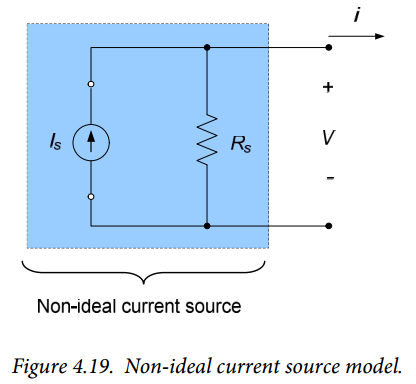
Practical current sources were modeled in section 2.4 as an ideal current source $I_S$ in parallel with some internal resistance $R_S$, as shown in Figure 4.19. This corresponds directly to a Norton equivalent circuit with $I_{SC} = I_S$ and $R_{TH} = R_S$. The current source provides maximum power to a circuit connected to it when the input resistance of the circuit is equal to the internal resistance of the source. A source transformation in conjunction with equation (5) indicates that the power delivered to the circuit by the current source is:
$$P= \frac{R_SI^2_S}{4}$$
Again, a reduced percentage of the power generated by the source will be delivered to the circuit when the circuit and source are not well matched.
Often, it may not be feasible to match the load with the power supply. For example, when we are testing circuits in our lab assignments we do not generally attempt to maximize the power delivered to the circuit – this is typical when prototype circuits are being tested. One simply recognizes that excessive power is being dissipated within the power supply and that the overall system is not functioning efficiently. If, however, the power supply and associated circuit are being designed as part of an integrated overall system one will generally attempt to match the power supply to the rest of the system.
One problem which can occur during circuit testing is that extremely poorly matched power supply-load combinations may result in so much power being dissipated within the power supply that insufficient power is available to drive the load. This can result in the load apparently behaving abnormally, unless power delivery effects are considered.
Section Summary
- The maximum power that a circuit can deliver to a load resistor occurs when the load resistance is equal to the Thévenin equivalent resistance of the circuit.


